THE ENGINE
A
rotates
the cylinder until the
next
recess
in
the lower
edge
of
the slot
comes
into
line with the
limiting
peg
and
prevents
the plunger
returning
to
its original
position and
allowing
the
timing
chain
to
become
slack
again.
When reassembling,
insert
the
spring
in
the plunger
and
place the cylinder
on
the other
end
of the
spring.
Compress
the
spring
until the cylinder
enters
the
plunger
bore,
engaging
the helical slot with
the
peg
in
the plunger.
Hold the assembly compressed
in
this
position
and
engage
the Allen key.
Turn
the
cylinder clockwise until the
end
of
the cylinder
is
below the
peg
and the
spring is
held
compressed. Withdraw the key and
insert
the plunger
assembly
in
the body. Replace the backplate
and
secure
the
assembly
to
the
cylinder
block.
After re■tting the
tensioner,
check the slipper head
for
freedom
of
movement
and
ensure
that
it
does
not
bind
on
the backplate
when
it is
moved
in
the
body.
When the
timing
chain
is
in position
the
tensioner is
released for
operation
by
inserting
the key
and
turning it
clockwise
until the slipper
head
moves
forward under
spring
pressure
against
the chain.
Do
not attempt to turn
the key anti-clockwise
or
force the
slipper
head
into
the chain
by
external
pressure.
Secure
the bolts with the locking
plate, replace
the bottom
plug, and lock with
a
tab washer.
Section
A.“
SUMP AND STRAINER
Drain the radiator and disconnect
the
hoses, drain the
sump,
and then release the
engine
front
mounting
bolts.
Sling
the
engine
and
lift
it
suf■ciently
to
gain
access
to
the
front
sump
bolts.
Remove
all the bolts
and withdraw
the
sump
from the
crankcase.
To
remove
the oil
strainer
remove
the
two
bolts
securing
it
to
the
pump
cover.
The
strainer
may
be dismantled
for cleaning by
removing
the
centre-nut
and
bolt
and the
two
delivery
pipe
■ange
bolts. Note
that there
is
a
locating
tongue
on
the
side of the
cover
which
must
be positioned
correctly when replacing.
Remember also
to
replace the
distance tube.
Clean
out
the
sump
and
strainer
with
paraf■n (kerosene)
and
a
stiff brush;
never use rag.
When
re■tting the
sump
to
the
engine give
particular
attention
to
the sealing gaskets
for
the crankcase
face
and
the
two
oil
seal
packings
for
the crankcase
which ■t
into
recesses
in
the crankcase.
If the gaskets
are
in
good condition
and have
not
been
damaged
during removal
of the
sump
they
may
be used
again,
but
it is
always
advisable
to
■t
new ones.
Before
■tting
new
gaskets
remove
all
traces
of the
old
ones
from
the
sump
and crankcase
faces.
Smear the faces of
the
crankcase joint
with
grease
and
■t
the
two
halves of the
large gasket. Lift the
sump
into position
on
the crankcase,
insert
the
19
bolts, and
tighten them evenly.
MGB. Issue
3. 1329
Re■t
the
engine
to
its
mountings
and the hoses
to
the
radiator. Re■ll the radiator and the
sump
with coolant
and
fresh
oil
respectively.
Section
A.12
OIL PUMP
Two
bolts
secure
the oil
pump cover
and three studs
secure
the
pump
to
the
crankcase.
Unscrew
the
stud
nuts
and
remove
the
pump
and drive shaft.
When re■tting the
pump use
a new
joint
washer.
Unscrew
the
two
securing
screws
and carefully
withdraw
the
cover,
which
is
located
on
the
base of the
oil
pump
body
by
two
dowels.
Withdraw the
outer
rotor,
and
the
inner
rotor
complete
with
oil
pump
shaft, from
the
pump
body.
Thoroughly
clean
all
parts
in
paraf■n (kerosene)
and
inspect
them
for
wear.
The
rotor
end-■oat
and
lobe
clearances
should
be checked
as
follows:
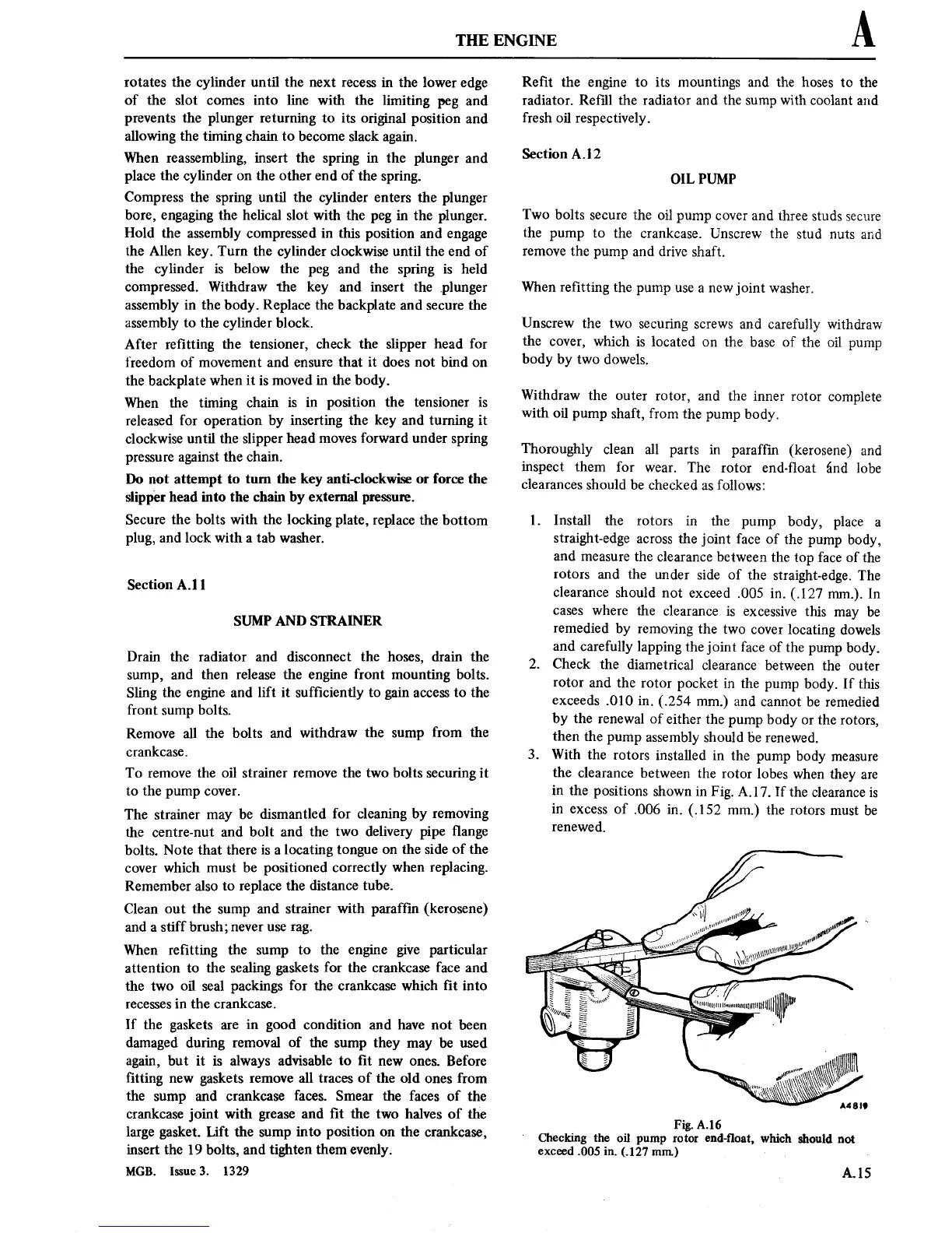
1. Install the
rotors
in
the
pump
body, place
a
straight-edge
across
the
joint face of
the
pump
body,
and
measure
the
clearance
between the
top
face of
the
rotors
and the
under side of the
straight-edge.
The
clearance
should
not
exceed
.005
in.
(.127
mm.).
In
cases
where the
clearance
is excessive
this
may
be
remedied by
removing
the
two
cover
locating
dowels
and carefully
lapping
the
joint
face
of the
pump
body.
2.
Check
the diametrical
clearance
between the
outer
rotor
and the
rotor
pocket
in
the
pump
body. If this
exceeds
.010
in.
(.254
mm.)
and
cannot
be remedied
by
the
renewal
of either the
pump
body
or
the
rotors,
then the
pump
assembly should
be
renewed.
3.
With
the
rotors
installed
in
the
pump
body
measure
the
clearance
between the
rotor
lobes
when they
are
in
the
positions
shown
in
Fig.
A.17.
If
the
clearance
is
in
excess
of
.006
in.
(.152
mm.) the
rotors
must
be
renewed.
Fig. A.16
Checking
the oil
pump
rotor
end-■oat,
which should
not
exceed
.005 in.
(.127 mm.)
A.15