THE IGNITION
SYSTEM
B
assembly,
capacitor,
cam,
rotor
arm
and their
associated
electrical
connections.
The
direction
of
rotation is
stamped
on
the
body.
The
upper
end
of
the
body
is
closed
by
a
bakelite
cap
which houses
the plug
lead
segments
and
the
HT.
lead
brush and
spring.
The
automatic
advance
mechanism
comprises
a
centrifugally
operated rolling
weight mechanism and
a
vacuum-operated
mechanism
which
together advance the
ignition point in
proportion
to
the
engine
speed and
load.
The
vacuum-operated
mechanism
has
a
vernier
adjustment
screw
to
enable small
adjustments
to
be made
to
suit
varying
grades
of fuel
or
to
satisfy
tuning requirements.
A
double-headed
arrow
marked
‘A’ and ‘R’
is
stamped
on
the
body
adjacent
to
the
vernier
screw.
A
fuel
trap
is
incorporated
in
the
vacuum
line
from the induction
manifold.
The
contact
breaker assembly
is
made
up
of
a
base plate
secured
to
the distributor body,
a
moving
contact
breaker
plate,
a
■xed
contact
breaker plate,
the
contact
breaker
points,
and
a
capacitor.
The
moving
plate
is
supported
on
the base plate by
two
nylon
pads,
which
minimizes
friction when the
automatic
advance
moves
the
plate.
A ‘C’
spring
anchored
to
a vacuum
control
spring
post
bears
against
the
under
side of the
base
plate
and
so
pre-tilts
the
moving
plate.
The
pressure
of
the
cam on
the
heel
of
the
contact
breaker
points
supplements
this
action
and
so
minimizes
rocking
of the
moving
plate
at
high
cam
speeds.
A
stud fixed
to
the under side of the
moving
contact
plate
engages
a
slot
in
the base plate
and
so
limits the
horizontal
movement
of the
moving
plate;
the
stud also
limits the
angle
of
tilt
of the
moving
plate.
The ■xed
contact
breaker plate
is
secured
by
a
screw
which
passes
through
a
slot
in
the
fixed plate.
A
notch
cut
in
the
free end
of
the plate
permits
the
engagement
of
a
screwdriver
for adjustment
purposes
when
setting
the
contact
breaker
points
gap.
The
distributor
is
secured
to
the
engine
by
a
split housing
plate and clamp
bolt. On
some
distributors the
clamp bolt
is
trapped and the
nut
free
and
on
others
the
nut
is trapped
and the bolt
is
free.
‘
Section
3.4
SERVICING THE DISTRIBUTOR
Contact
breaker
points
Examine
the
contact
breaker
points
and
if
they
are
found
to
be burnt
or
blackened
remove
them
as
described
in
Section
B.6
and clean
them
with
a
■ne carborundum
stone
or
emery-cloth.
After
cleaning,
remove
all
traces
of
dust and
grease
with
a
petrol-moistened
cloth.
Lightly
smear
the
contact
breaker
pivot
pin
with
molybdenized
non-creep
oil
or a
suitable
grease
and
re■t
the
points.
it is important
that
no
oil
or
grease
is
allowed
to
contaminate
the
contact
breaker
points.
MGB.
Issue4. 1329
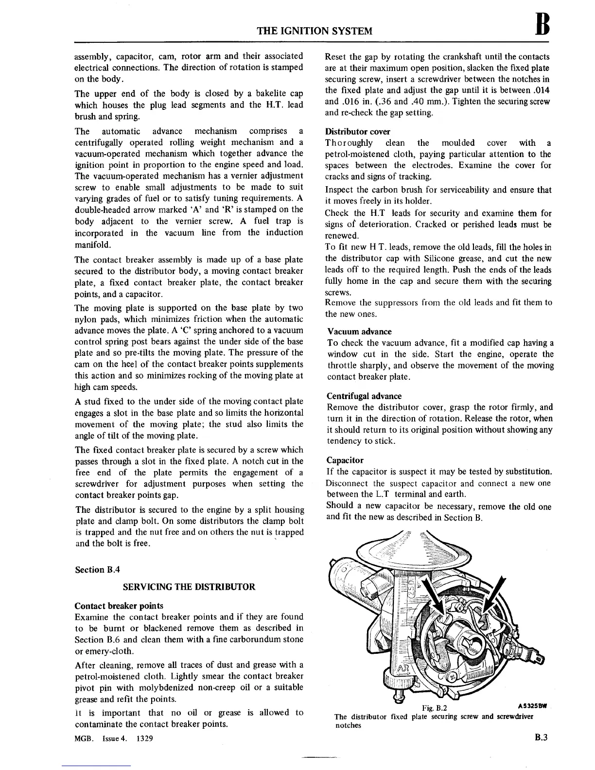
Reset
the
gap
by
rotating
the
crankshaft
until
the
contacts
are
at
their
maximum
open
position,
slacken the ■xed plate
securing
screw,
insert
a
screwdriver between the notches
in
the ■xed plate and adjust
the
gap
until
it is
between
.014
and
.016
in.
(.36
and
.40
mm.).
Tighten
the
securing
screw
and
re-check the
gap
setting.
Distributor
cover
Thoroughly clean the moulded
cover
with
a
petrol-moistened cloth,
paying
particular
attention
to
the
spaces
between
the
electrodes. Examine
the
cover
for
cracks and
signs
of
tracking.
Inspect
the carbon brush for
serviceability
and
ensure
that
it
moves
freely
in its
holder.
Check
the HT leads
for
security
and
examine
them
for
signs
of
deterioration.
Cracked
or
perished leads
must
be
renewed.
To
■t
new
H T. leads,
remove
the old leads, fill
the holes
in
the
distributor
cap
with Silicone
grease,
and
cut
the
new
leads off
to
the required length. Push the
ends
of the leads
fully home
in
the
cap
and
secure
them with the
securing
screws.
Remove the
suppressors
from
the old
leads and
fit them
to
the
new ones.
Vacuum
advance
To
check
the
vacuum
advance,
■t
a
modified
cap
having
a
window
cut
in
the side.
Start
the
engine,
operate
the
throttle sharply, and observe the
movement
of
the
moving
contact
breaker plate.
Centrifugal advance
Remove
the distributor
cover,
grasp
the
rotor
firmly, and
turn
it in
the direction
of
rotation.
Release the
rotor,
when
it
should
return
to
its
original
position
without showing
any
tendency
to
stick.
Capacitor
If the
capacitor is
suspect
it
may
be tested by substitution.
Disconnect the
suspect
capacitor
and
connect
a
new
one
between the LT terminal and
earth.
Should
a new
capacitor
be
necessary,
remove
the
old
one
and ■t
the
new
as
described
in Section B.
A5325“
Fig. 3.2
The
distributor ■xed
plate securing
screw
and screwdriver
notches
B.3