THE BODY
B
Remove the ‘C’ clip
retaining
the
remote
control
link
to
the
door lock and detach the link.
Remove the
screws
securing
the
lock
to
the door and withdraw the
lock assembly.
TOURER
(EARLY
MODELS)
Remove the
inner
door handle, door pull,
and
window
regulator handle
(Section R.8).
Remove the door
trim
pad
and
door glass assembly
(Sections
RA and
R6).
Disconnect the remote-control
link by
unscrewing
the
two
screws,
remove
the three
screws
securing
the
remote-control
mechanism
to
the
door,
and
withdraw the mechanism from
the
rear access
panel.
Remove the
two
screws
securing
the
outer
door handle,
disengage the handle from
the lock, and
remove
it
from the
door. From inside
the door panel slide the
retaining
clip
from
the barrel
of
the
private
lock
and withdraw the
lock
barrel and the coupling
link
from
the
outside of the door.
Remove the four
screws
securing
the lock
to
the
door and
withdraw the lock.
Re■tting
Reverse the
removing operations, noting
that the latch
must
be
in
the
open
position
when refitting
the lock
to
the
door,
and that
the locking lever
must
be
engaged with the
private
lock
operating
fork. Check for
correct
functioning
(Secttion
R.9).
Tourer
(early models)
Reverse the
removal
sequence.
Elongated holes
in
the
door
panel will
allow
the
remote-control mechanism
to
be
correctly adjusted. After re■tting
lubricate
the lock
assembly and check
it
for
correct
functioning.
Section R.ll
DOOR
LOCK
REMOTE CONTROL
UNIT
(Later Models and GT)
Removing
7
Remove the
inner
door handle, door pull, and window
regulator handle
(Section R.8).
Remove the
trim
pad
(Section R.4).
Detach the
remote
control link from
the
door
lock by
removing
the ‘C’
retaining
clip:
Remove the
screws
securing
the
remote
control
unit
to
the
door.
Remove the moulded rubber hood
covering
the
upper
end
of the
window
run
channel, from the
top
of
the front
quarter-light.
Remove the
nut
securing
the window regulator
upper
limit
stop
and
remove
the
stop.
Wind the window
up
until the
lifting
studs
can
be disengaged from the lifting
channel.
Remove
the
screws
securing
the lower
end
of the front
window
run
channel.
Retain the glass
in
the
up
position
with
wedges
or remove
it
from the
door.
Remove
the window regulator
securing
screws.
Press the
window
regulator and front window
run
channel
away
from
the
inner
door
panel and withdraw
the
remote
control
unit
MGB.
Issue3.
1329
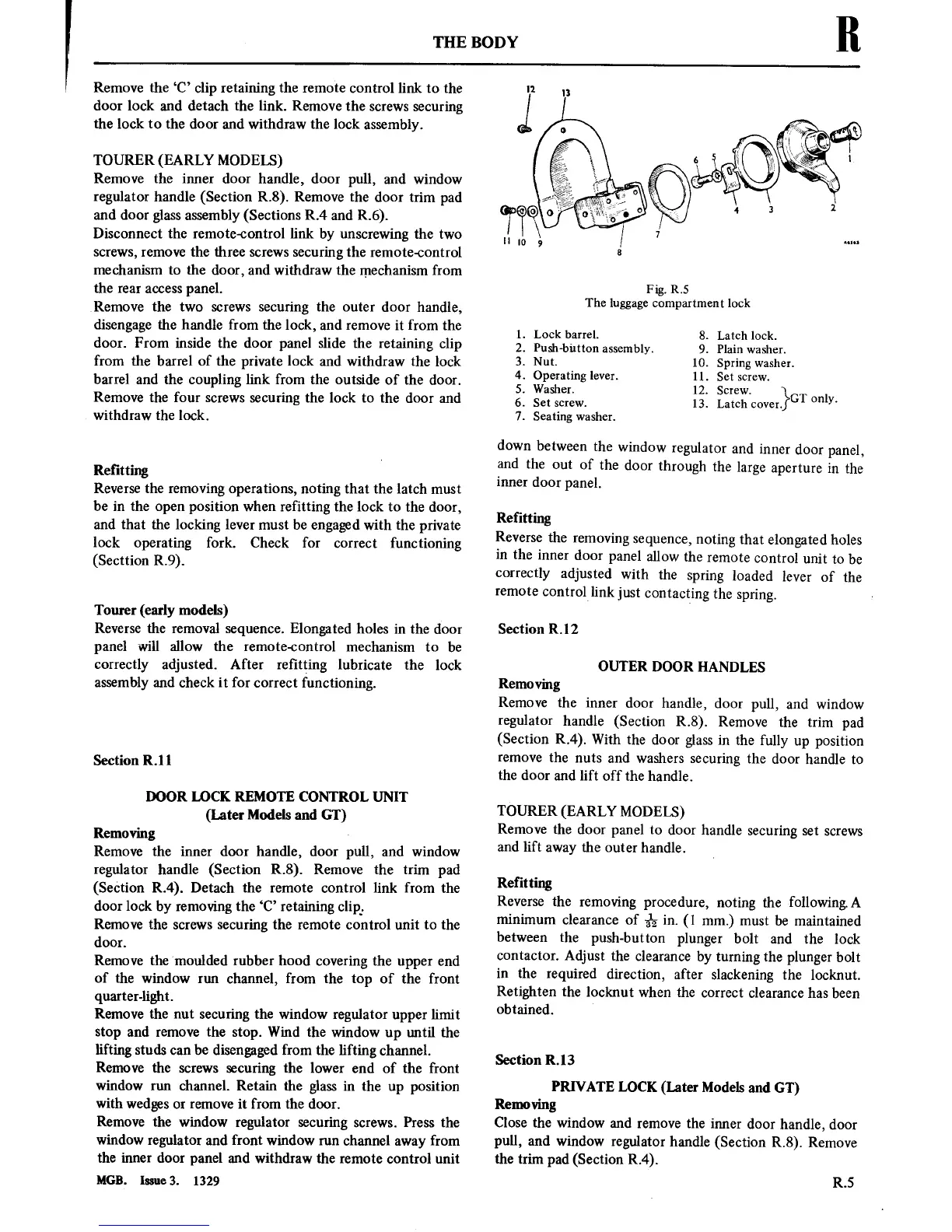
Fig.
R.5
The
luggage
compartment
lock
1. Lock
barrel.
8.
Latch lock.
2. Push-button
assembly. 9.
Plain
washer.
3.
Nut.
10. Spring
washer.
4. Operating
lever.
11. Set
screw.
5. Washer.
12.
Screw.
6.
Set
screw.
13.
Latch
cover}GT
only‘
7.
Seating
washer.
down
between
the
window
regulator
and
inner door
panel,
and the
out
of
the
door
through
the
large
aperture
in
the
inner door
panel.
Refitting
Reverse
the
removing
sequence,
noting
that
elongated holes
in
the
inner door
panel
allow
the
remote
control
unit
to
be
correctly
adjusted
with
the
spring
loaded
lever
of
the
remote
control link
just
contacting
the
spring.
Section
R. l
2
OUTER
DOOR
HANDLES
Removing
Remove the
inner
door
handle,
door
pull,
and
window
regulator
handle (Section
R.8).
Remove
the
trim
pad
(Section
R.4).
With the
door glass
in
the
fully
up
position
remove
the
nuts
and
washers
securing
the
door handle
to
the
door and lift
off
the handle.
TOURER
(EARLY
MODELS)
Remove the door
panel
to
door handle
securing
set
screws
and lift
away
the
outer
handle.
Refitting
Reverse the
removing
procedure,
noting
the
followingA
minimum clearance
of
3%
in.
(1 mm.)
must
be
maintained
between
the
push-button
plunger bolt
and the
lock
contactor.
Adjust
the clearance
by
turning
the plunger
bolt
in
the
required
direction, after
slackening
the locknut.
Retighten the
locknut
when the
correct
clearance has
been
obtained.
Section R.l3
PRIVATE
LOCK
(Later
Models
and GT)
Removing
Close
the window
and
remove
the
inner
door
handle,
door
pull,
and window
regulator handle (Section
R.8).
Remove
the
trim
pad
(Section
R.4).
R.5