K
THE
FRONT
SUSPENSION
:u
.
'
8.
Extract the split
pin
from
the
swivel
axle and
remove
the
nut,
upper
trunnion suspension
link, steel and
bronze
thrust washers,
swivel
pin,
and dust
covers
and
spring.
From the
swivel
pin
remove
the
cork washer.
Examination
Wash
all
parts
and
thoroughly dry them with
a
non-■uffy
cloth. Examine all
parts
for
wear or
damage,
paying
particular
attention
to
the swivel
pins,
lower
fulcrum
pins,
and all bushes. Check
the
pins
for ovality. Worn
or
suspect
pins
or
bushes
must
be renewed.
Assembling
and replacing
Reverse
the
dismantling
sequence
to
reassemble the
ax1es,
and,
if
necessary,
renew
the thrust
washers by
selective
assembly
to
produce
a
condition
that will
permit
the swivel
axle
to
rotate
freely
on
the
pin
with
a
minimum
amount
of
end-play. The
maximum
permissible
end-play
is
.002
in.
(.05 mm.).
The
thrust
washers
are
available
in
the
following
sizes:
.052
to
.057
in.
(1.32
to
1.44
mm),
.058
to
.063
in.
(1.47
to
1.60
mm.),
.064
to
.069
in.
(1.62
to
1.75
mm.).
After assembly
reverse
the removal
sequence
to
re■t
the
assembly
to
the hub.
a
Section K.5
REMOVING AND REFITTING BUSHES
Swivel pin bush
'
1.
Press
out
the old bushand
ensure
that the lubrication
“
channels
are
clean and
free
from
obstruction.
'
0
2.
Position
the
new
bush with
:the
split
in
the bush
adjacent
to
the
outef‘face
of'fhe
base. This will
ensure
that the
grease
channel
in
the .bush
is in
line with the
.
chahnel
in
the
pin.
'
'
Al562
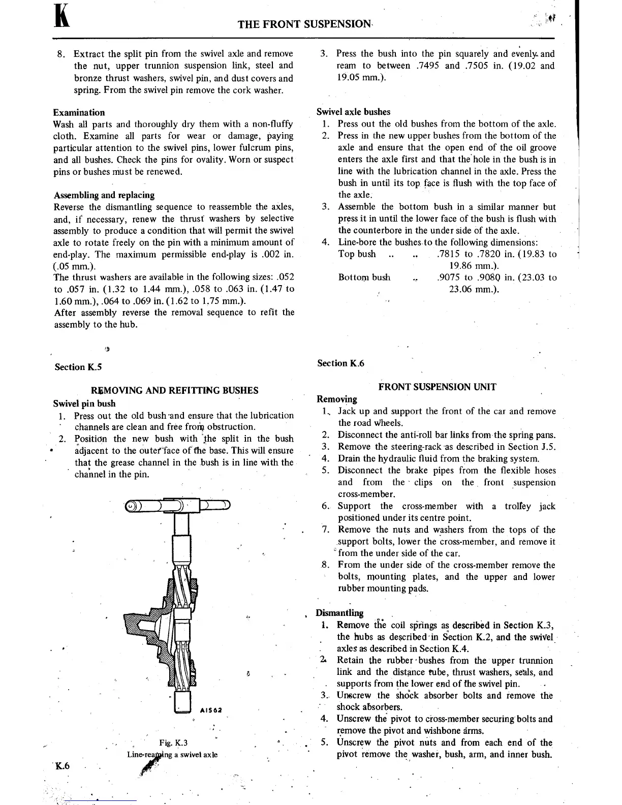
Fig. k3
"
,
°.
~
.
_
“
Line-rea
ingaswivel
axle
K.6
.
.
,
3.
Press the bush
into
the
pin
squarely
and
evenly.
and
ream
to
between .7495 and
.7505
in.
(19.02
and
19.05
m.).
V
Swivel axle bushes
1.
Press
out
the old bushes
from
the bottom of the axle.
2.
Press
in
the
new
upper
bushes from the
bottom
Of
the
axle and
ensure
that the
open
end of the oil
groove
enters
the axle first
and that
thehole
in
the bush
is in
line with the
lubrication channel
in
the
axle. Press the
bush
in
until
its
top,
face
is
■ush
with the
top
face of
the
axle. '
3. Assemble the
bottom
bush
in
a
similar
manner
but
press
it in
until the lower face of
the bush
is
flush
with
the
counterbore
in
the under side of the
axle.
‘
4. Line—bore the bushesto the following
dimensions:
Top bush
.7815
to
.7820
in.
(19.83
to
‘
19.86
mm.).
Bottom
bush
.9075
to
.9080
in.
(23.03
to
23.06
mm.).
Section
K.6
FRONT
SUSPENSION UNIT
Removing
1.,
Jack
up
and
support
the front of the
car
and
remove
the road w'heels.
‘
2. Disconnect the anti-roll bar links fromthe
spring
pans.
3.
Remove the
steering-rackas described
in
Section J.5.
4.
Drain the hydraulic ■uid from
the braking
system.
5. Disconnect the brake
pipes
from the ■exible
hoses
and from the
‘
clips
on
the
,
front
suspension
cross-member.
v
6. Support the
cross-member with
a
trolley
jack
positioned
under
its
centre
point.
‘7.
Remove the
nuts
and washers from the
tops
of the
,support
bolts, lower the
cross-member, and
remove
it
from
the
under Side
of
the
car.
.8. From the
under side of the
cross-member
remove
the
bolts,
mounting
plates, and the
upper
and lower
rubber
moUnting
pads.
,
Dismantling
1.
Remove
the
coil
Springs
as
described
in
Section
K3,
the
hubs
as
describedin
Section K2, and the SWiVel-
axles
as
described
in
Section
K.4.
'
'
'
2s
Retain the
rubbercbushes from the
upper
trunnion
link
and the
distance
tube,
thrust washers, seals,
and
supports
from
the lower end of the swivel
pin.
3.. Unscrew the
shdck
absorber bolts and remove the
t
'
‘
shock
absorbers.
-
4. Unscrew
the
pivot
to
cross-member
securing
bolts
and
‘
‘
remove
the
pivot
and wishbone
arms.
*
5. Unscrew the
pivot
nuts
and
from
each end of the
pivot
remove
the■washer, bush,
arm,
and
inner
bush.