THE BRAKING SYSTEM
M
Removing
the calliper
pistons
Unscrew
and
remove
the
two
bolts
securing
the calliper
to
the front hub and withdraw the calliper from the disc and
hub. Do
not
remove
the
rubber hose, and
support
the
calliper
to
avoid
straining
the hose.
Remove
the friction
pads and
clean
the outside
of
the calliper, making
sure
that
all dirt and
traces
of cleaning ■uid
are
completely
removed.
Clamp the
piston
in
the
mounting
half of the calliper
and
gently
apply
the
foot brake. This
operation
will
force the
piston in
the
rim
half of the calliper
to
move
outwards.
Continue with gentle
pressure on
the foot pedal
until
the
piston
has
emerged
suf■ciently for
it
to
be removed by
hand.
Have
a
clean
receptacle ready
to
catch the ■uid
as
the
piston is
removed.
With
a
suitable blunt-nosed tool
remove
the
■uid
seal
from
its
groove
in
the bore
of the
calliper, taking
great
care
not
to
damage the bore
of the calliper
or
the seal
retaining
groove.
The dust
seal
retainer
can
be removed
by
inserting
a
screwdriver between the
retainer
and
the seal and gently
prising
the
retainer
from the mouth of the calliper bore.
The rubber seal
can
then
be detached.
Remove
the clamp from
the mounting-half
piston.
To
remove
the
mounting-half
piston
from the calliper
it is
necessary
■rst
to
re■t
the
rim-half
piston,
and
thereafter
the procedure
is
as
previously
detailed.
When cleaning
out
the
calliper
it is
essential
that
only
methylated
spirit
or
Lockheed Brake
Fluid be used
as a
cleaning medium.
Other
types
of
cleaning
■uid
may
damage
the internal rubber
seal between
the
two
halves of the
calliper.
\\\\\\:\\\
\‘31
mMW
A 607
7
Fig. M.5
A
disc
brake in section
1. Calliper—mounting half.
5.
Friction
pad.
2. Calliper—rirnhalf. 6. Dust sealretainer.
3 Hydraulic piston.
7. Dust seal.
4. Padbacking
plate. 8.
Fluid
seal.
MGB. IssueZ.
1329
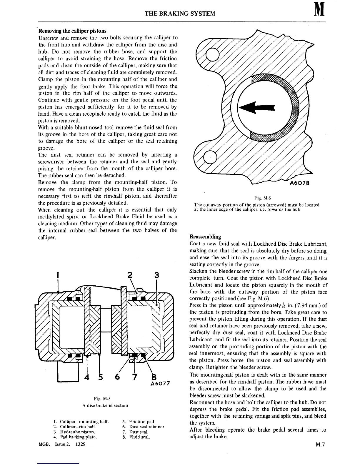
Fig. M.6
The
cut-away
portion of the
piston (arrowed)
must
be located
at
the
inner
edgeof the calliper, i.e.
towards the hub
Reassembling
Coat
a new
■uid
seal with
Lockheed
Disc Brake Lubricant,
making
sure
that the seal
is
absolutely dry before
so
doing,
and
ease
the seal
into its
groove
with
the
■ngers
until
it is
seating
correctly
in
the
groove.
Slacken the
bleeder
screw
in
the
rim
half of the calliper
one
complete
turn.
Coat the
piston
with
Lockheed
Disc Brake
Lubricant
and locate the
piston
squarely
in
the mouth of
the bore
with the
cutaway
portion
of the
piston
face
correctly
positioned
(see
Fig.
M.6).
Press
in
the
piston
until
approximately—1%
in.
(7.94
mm.)
of
the
piston
is
protruding from the bore.
Take
great
care
to
prevent
the
piston
tilting during this
operation.
If
the dust
seal
and
retainer
have
been previously
removed, take
a
new,
perfectly dry
dust seal,
coat
it
with Lockheed
Disc Brake
Lubricant,
and ■t the
seal
into its retainer.
Position the seal
assembly
on
the protruding
portion
of the
piston
with the
seal
innermost,
ensuring
that the
assembly
is
square
with
the
piston.
Press home the
piston
and seal assembly with
clamp.
Retighten the bleeder
screw.
The mounting-half
piston is
dealt with
in
the
same manner
as
described for the rim-half
piston.
The rubber hose
must
be disconnected
to
allow the clamp
to
be used
and the
bleeder
screw
must
be slackened.
Reconnect
the hose and bolt the calliper
to
the
hub.
Do
not
depress the brake pedal. Fit
the friction pad assemblies,
together with the
retaining springs
and split
pins,
and
bleed
the
system.
After bleeding
operate
the brake pedal several
times
to
adjust the brake.
M.7