THE
ENGINE
A
The
upper
ends
of the choke
return
springs
are
fitted
to
the
cam
levers
of
the forward
and
rear
carburetters
and the
lower
ends
to
clips
on
the bottom
of the heat
shield.
To
remove
the accelerator control take
off the
air
cleaners
as
detailed
in
Section
D, release
the
inner
cable
from
the
spindle and
lever assembly and withdraw
the
inner
cable
from the
outer
cable
at
the pedal end.
Release
the
accelerator
cable
clip
in
the
engine
compartment
and
remove
the
outer
cable.
Unscrew
the pedal assembly
fulcrum
bolt from the pedal
bracket
and
remove
the pedal,
bush, and distance
piece.
Replacement
is
a
reversal
of the removal
sequence.
After replacement
ensure
that the control
is
adjusted
correctly
as
detailed
in
Section
D.
To
remove
the choke control release
the
inner
cable
from
the
pin
on
the choke control bracket and
retain
the cable
abutment.
Free
the
grommet
from
the bulkhead.
From the
rear
of the
fascia
panel
unscrew
the
securing
nut
and withdraw
the assembly
from the fascia.
Replacement is
a
reversal
of the
removal
sequence.
After replacing
the accelerator
and
choke controls
ensure
that
they
are
correctly
adjusted
as
detailed
in
Section
D.
Section
A.23
EXHAUST
SYSTEM
The
exhaust
system
is
made
up
of
a
front
pipe
and junction
assembly,
a
front intermediate
pipe,
a
front silencer,
a
rear
intermediate
pipe,
and
a
rear
silencer
and tail
pipe.
The
assembly
is
welded together.
The
front
pipe
and
junction
assembly
mate
with the
exhaust
manifold
ports;
joint
washers
are
■tted
to
each
pipe.
The front
intermediate
pipe is
supported
by
a
clip
which
is
attached
to
a
strap
and
bracket. The bracket
is
bolted
to
the
lower
■ange of the gearbox.
A
rubber
mounting
bolted
to
the
rear
frame
member
supports
a
bushed housing
to
which
is
attached
the front
silencer mounting
bracket.
A
second rubber
mounting
bolted
to
the
rear
frame
embodies
a
split
clamp that
secures
the
tail
pipe.
To
remove
the
exhaust assembly
remove
the
six
nuts
from
the
manifold
port
studs,
allow the
twin pipes
to
drop,
and
retain
the joint
washers.
Loosen
the
rear
mounting
tail
pipe
securing
bolt,
remove
the front
silencer
support
clip bolt, and
draw the
assembly
forward and
downward.
To
re■t the assembly
reverse
the removal
sequence
but
leave the
front
silencer
and tail
pipe
securing
bolts slack
until
the
twin
down
pipes
and
joint
washers have
been
■tted and
tightened. Tighten
the silencer
clip
bolt
and
■nally the
split
clamp bolt
on
the tail
pipe.
MGB.
Issue
9. 80619
*
'-
\
/:
:
r
C
a
\t
,
1
\\
1
I
\
;
\
’HnuH‘
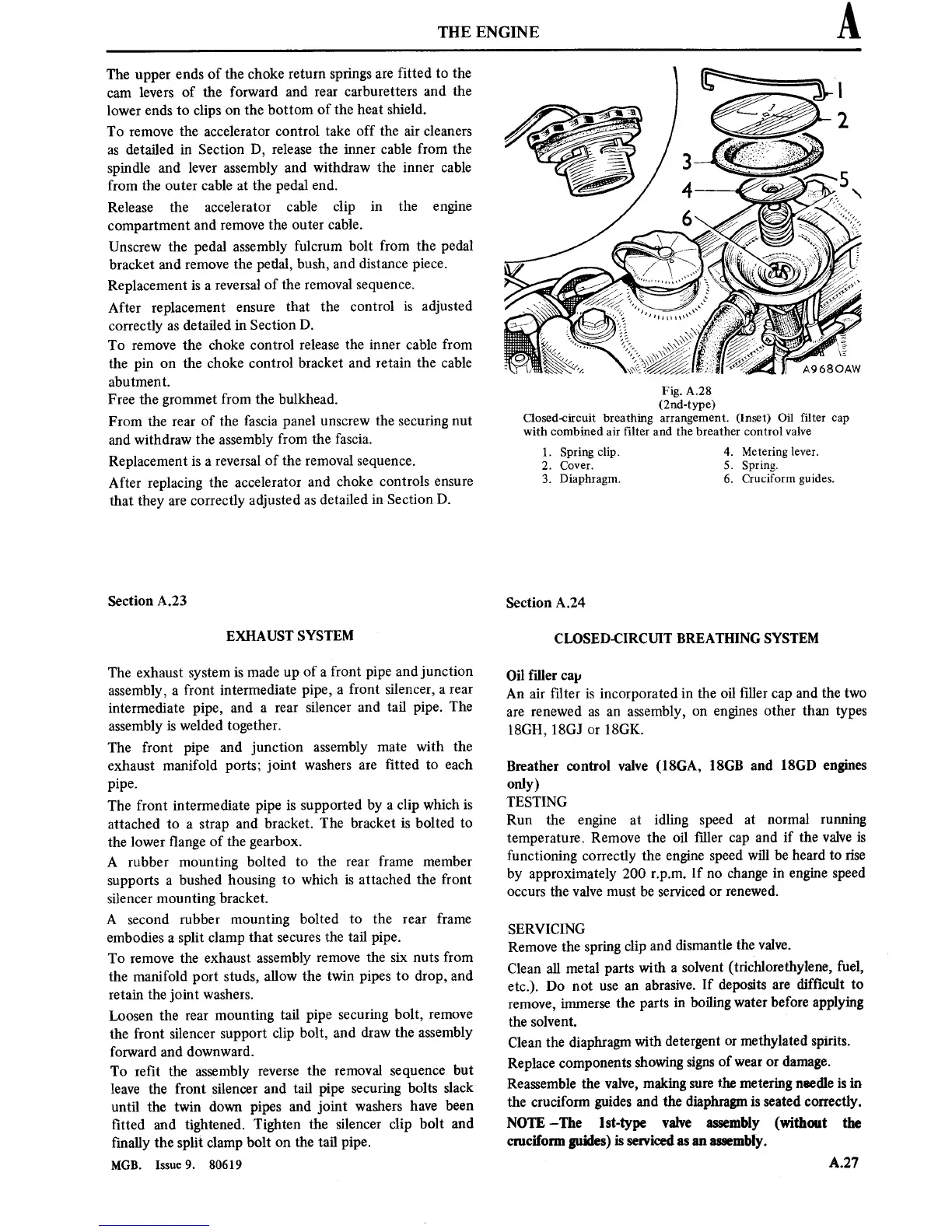
Fig.
A28
(2nd-type)
Closed-circuit breathing
arrangement.
(Inset) Oil
■lter
cap
with combined
air
■lter and the breather control valve
1.
Spring clip.
2. Cover.
3. Diaphragm.
4.
Metering lever.
5. Spring.
6.
Cruciform guides.
Section
A.24
CLOSED-CIRCUIT BREATHING SYSTEM
Oil filler
cap
An air
■lter
is
incorporated
in
the oil
■ller
cap
and the
two
are
renewed
as an
assembly,
on
engines
other than
types
18GH, 18G]
or
18GK.
Breather
control valve (18GA, 18GB
and 18GB engines
only)
TESTING
Run
the
engine
at
idling
speed
at
normal
running
temperature.
Remove
the oil
■ller
cap
and
if the valve
is
functioning correctly the
engine
speed will be
heard
to
rise
by approximately 200
rpm.
If
no
change
in engine
speed
occurs
the valve
must
be serviced
or
renewed.
SERVICING
Remove
the
spring
clip
and
dismantle the valve.
Clean
all
metal
parts
with
a
solvent
(trichlorethylene,
fuel,
etc.).
Do
not
use an
abrasive.
If deposits
are
dif■cult
to
remove,
immerse
the
parts
in
boiling
water
before applying
the solvent.
Clean
the
diaphragm
with detergent
or
methylated
spirits.
Replace
components
showing
signs
of
wear or
damage.
Reassemble the
valve,
making
sure
the
metering
needle
is in
the
cruciform guides and
the
diaphragm
is
seated correctly.
NOTE
—The
lst-type valve assembly (without
the
cruciform guides)
is
serviced
as an
assembly.
A.27