N
THE
ELECTRICAL
SYSTEM
16.
Unscrew
the
two
brush moulding securing
screws.
17.
Slacken
the
recti■er
pack retaining
nuts
and
withdraw
the brush
moulding
and
recti■er pack.
BRUSHES
18.
Check
the
brushes for
wear
by measuring
the
length of
brush protruding
beyond the
brushbox
moulding.
If
the
length
protruding
is
.2
in.
(5
mm.)
or
less
the
brush
must
be
renewed.
19.
Check
that
the brushes
move
freely
in
their holders.
If
a
brush shows
a
tendency
to
stick,
clean
it
with
a
petrol
(gasoline) moistened cloth
or,
if
necessary
polish the sides
of the
brush with
a
fine ■le.
20.
Check the
brush
spring
pressure
using
a
push-type
spring
gauge.
The
gauge
should
register
7
to
10
oz.
(198
to
283
gm.)
when
the
brush
is
pushed back until
its
face
is
■ush with
the housing.
If
the
gauge
reading
is
outside
the limits
given,
renew
the
brush assembly.
SLIP-RINGS
21.
Clean
the
surfaces
of
the slip-rings
using
a
petrol
(gasoline) moistened cloth.
22. Inspect
the slip-ring
surfaces for
signs
of burning;
remove
burn
marks
using
very
■ne sand-paper. On
no
account
must
emery-cloth
or
similar abrasives
be used
or
any
attempt
made
to
machine
the slip-rings.
ROTOR
23.
Connect
an
ohmmeter
or
a
12-volt
battery
and
an
ammeter
to
the slip-rings. An
ohmmeter
reading of 4.3
ohms
or an
ammeter
reading
of
3
amps.
should be
recorded.
24.
Using
a
llO-volt A.C’
supply and
a
15-watt
test
lamp,
test
for insulation between
one
of the slip-rings and
one
of the
rotor
poles.
If the
test
lamp
lights the
rotor
must
be
renewed.
STATOR
25.
Connnect
a
12-volt battery
and
a
36-watt
test
lamp
to
two
of
the
stator
connections.
Repeat
the
test
replacing
one
of
the
two
stator
connections
with the
third. If the
test
lamp
fails
to
light
in
either
of
the
tests
the
stator
must
be
renewed.
26.
Using
a
llO-volt A.C.
supply and
a
lS-watt
test
lamp,
test
for insulation between
any one
of
the
three
stator
connections
and the
stator
laminations.
If the
test
lamp lights,
the
stator must
be
renewed.
DIODES
27.
Connect
a
l2-volt
battery
and l.5-watt
test
lamp
in
turn to
each of the
nine
diode
pins
and
its
corresponding heat
sink
on
the recti■er pack, then
reverse
the
connections.
The lamp should light with
the
current
flowing
in
one
direction
only. If the
lamp
lights
in
both directions
or
fails
to
light
in
either, the
recti■er pack
must
be renewed.
N30
IMPORTANT.—See
notes
on
soldering the
diodes
givenin2.
DISMANTLING
28.
Carry
out
the
operations
detailed
in
14
to
17.
29. Remove
the three
through-bolts.
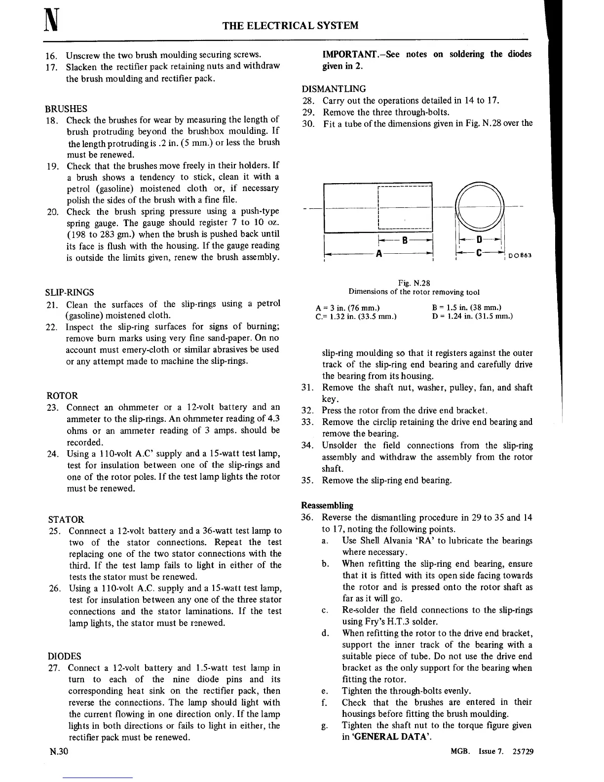
30.
Fit
a
tube
of the dimensions given
in
Fig. N.28
over
the
1+4
©
l<——B
A
,Doaea
Fig. N.28
Dimensions
of
the
rotor
removing
tool
=
B
=
1.5
in. (38 mm.)
.=
.32 in. (33.5 mm.)
D
=
1.24
in.
(31.5 mm.)
slip-ring moulding
so
that
it
registers
against
the
outer
track of the slip-ring end bearing
and
carefully drive
the
hearing from
its
housing.
31. Remove
the shaft
nut,
washer,
pulley,
fan,
and shaft
key.
32.
Press the
rotor
from the drive end bracket.
33.
Remove the circlip
retaining
the drive end bearing and
remove
the bearing.
34. Unsolder the ■eld
connections
from the slip-ring
assembly and withdraw the
assembly from the
rotor
shaft.
35.
Remove the slip-ring end bearing.
Reassembling
36. Reverse the dismantling
procedure
in 29
to
35 and 14
to
17,
noting
the following
points.
21.
Use Shell Alvania
‘RA’
to
lubricate
the bearings
where
necessary.
b. When re■tting the
slip-ring end bearing,
ensure
that
it is
■tted
with
its
open
side facing towards
the
rotor
and
is
pressed
onto
the
rotor
shaft
as
far
as
it
will
go.
c.
Re-solder the ■eld
connections
to
the slip-rings
using
Fry’s
H.T.3 solder.
d. When re■tting
the
rotor to
the
drive end
bracket,
support
the
inner
track
of
the bearing with
a
suitable
piece
of
tube. Do
not
use
the drive end
bracket
as
the only
support
for
the
bearing when
■tting
the
rotor.
e.
Tighten the through-bolts
evenly.
f. Check that
the
brushes
are
entered
in
their
housings
before
■tting
the brush moulding.
g.
Tighten the
shaft
nut to
the
torque
■gure
given
in
‘GENERAL DATA’.
MGB.
Issue7. 25729