THE ELECTRICAL
SYSTEM
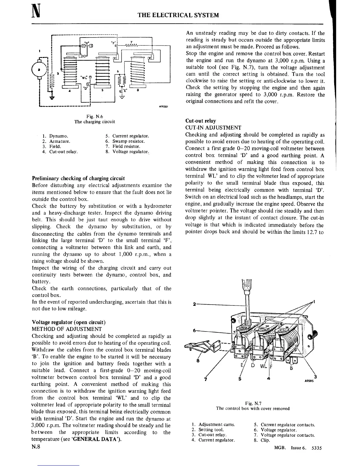
Fig. N13
The charging
circuit
1.
Dynamo. 5. Current regulator.
2.
Armature.
6. Swampresistor.
3.
Field. 7. Field resistor.
4. Cut-out
relay. 8.
Voltage
regulator.
Preliminary checking
of
charging circuit
Before disturbing
any
electrical adjustments
examine
the
items
mentioned
below
to
ensure
that the fault
does
not
lie
outside
the
control
box.
Check the battery by substitutionor with
a
hydrometer
and
a
heavy-discharge
tester.
Inspect
the dynamo driving
belt.
This should be
just
taut
enough
to
drive without
slipping.
Check the
dynamo
by
substitution,
or
by
disconnecting the
cables from the dynamo
terminals and
linking the large terminal ‘D’
to
the small terminal ‘F’,
connecting
a
voltmeter between this link and earth, and
running
the dynamo
up
to
about 1,000
rpm,
when
a
rising
voltage should be shown.
Inspect
the
wiring
of
the charging
circuit
and
carry
out
continuity
tests
between the dynamo, control box,
and
battery.
Check the
earth
connections,
particularly that of the
control box.
In
the
event
of
reported undercharging,
ascertain
that this
is
not
due
to
low
mileage.
Voltage regulator (open
circuit)
METHOD OF ADJUSTMENT
Checking and adjusting should be
completed
as
rapidly
as
possible
to
avoid
errors
due
to
heating
of the
operating
coil.
Withdraw the cables from the
control box
terminal blades
‘B’. To enable the
engine
to
be started
it
will
be
necessary
to
join
the
ignition
and battery feeds
together with
a
suitable lead. Connect
a
first-grade
0—20
moving-coil
voltmeter between control box
terminal ‘D’
and
a
good
earthing
point.
A
convenient
method of
making this
connection is
to
withdraw the
ignition
warning
light
feed
from the
control box
terminal ‘WL’ and
to
clip the
voltmeter lead
of
appropriate
polarity
to
the
small
terminal
blade thus exposed, this terminal being
electrically
common
with terminal
‘D’. Start
the
engine
and
run
the
dynamo
at
3,000
rpm.
The voltmeter reading should
be steady
and lie
between
the
appropriate
limits
according
to
the
temperature
(see
‘GENERAL
DATA’).
N.8
An
unsteady
reading
may
be due
to
dirty
contacts.
If the
reading
is
steady but
occurs
outside the
appropriate
limits
an
adjustment
mu
st
be made. Proceed
as
follows.
Stop the
engine
and
remove
the
control
box
cover.
Restart
the
engine
and
run
the dynamo
at
3,000
rpm.
Using
a
suitable tool
(see
Fig. N.7),
turn
the
voltage
adjustment
cam
until the
correct
setting is
obtained.
Turn the
tool
clockwise
to
raise
the
setting
or
anti-clockwise
to
lower
it.
Check
the
setting
by
stopping
the
engine
and then
again
raising
the
generator
speed
to
3,000
rpm.
Restore
the
original
connections
and refit the
cover.
Cut-out relay
CUT-IN
ADJUSTMENT
Checking
and adjusting should be completed
as
rapidly
as
possible
to
avoid
errors
due
to
heating of the
operating
coil.
Connect
a
first
grade
0—20
moving-coil
voltmeter
between
control box terminal ‘D’ and
a
good earthing
point. A
convenient
method of making this
connection is
to
withdraw the
ignition
warning
light feed from
control
box
terminal WL’
and
to
clip the voltmeter
lead
of
appropriate
polarity
to
the
small terminal blade
thus
exposed, this
terminal
being electrically
common
with
terminal ‘D’.
Switch
on
an
electrical
load such
as
the
headlamps,
start
the
engine,
and gradually
increase
the
engine
speed. Observe
the
voltmeter
pointer.
The voltage should
rise
steadily
and then
drop slightly
at
the
instant
of
contact
closure. The
cut-in
voltage
is
that which
is
indicated
immediately
before
the
pointer
drops back
and
should be
within the limits
12.7
to
3
7
5
4
A9555
Fig.
N.7
The
control
box with
cover
removed
1.
Adjustment
cams.
5. Current
regulator
contacts.
2.
Setting tool.
6. Voltage
regulator.
3. Cut-out relay.
7. Voltage
regulator
contacts.
4.
Current regulator.
8. Clip.
MGB.
Issue6.
5335