A
THE
ENGINE
Section
A.32
Re■ning
6. I
t
h
'
'
' '
r
v
53:: ii:
13:: ‘2‘:.:“.:“;‘::;:;:;a.:“%mar:
(Later
engines)
188
g P, P
g
.
p
Remove
and re■t the
rocker
assembly
as
detailed
in
Section
A.5, noting
the following:
Section
A.33
VALVE
GEAR
Em
C
(Single
Valve Spring)
“v2
Removing
1.
Remove
the cylinder
head~see
Section
A.6.
2.
Compress
the
valve
spring, using
18G 45,
and
remove
the
valve
cotter.
3.
Release
the
spring
compressor
and
remove
the
valve/
collar, valve
spring
and
valve spring
cup.
4. Remove
the packing
ring
and
withdraw the
valve
from
its
guide.
5. Remove
each
valve assembly
in
turn
and
retain
in
their
(3)
Fit
a
0.005
in.(0.l3
mm.)
shim under
the
two
centre
brackets.
These shims
should be
fitted
to
early
engines
on
reassembly.
(b)
Later
engines,
identified
by
single
valve
springs,
have
bucket-type
tappets,
longer
push-rods and
a
longer
thread
on
the
rocker adjusting
screws
which
are
interchangeable
as a
set
with the
■rst-type
assembly.
installed order.
MGB.
3NC
958
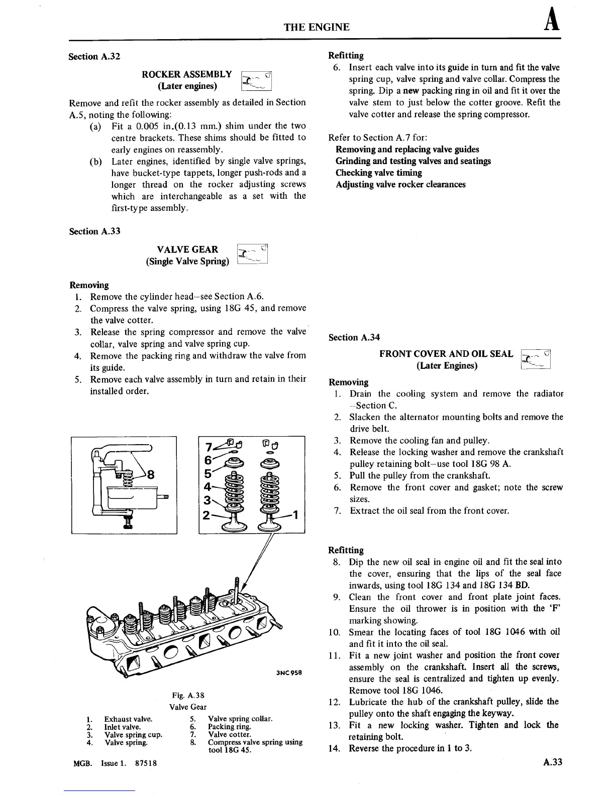
Fig.
A.38
Valve
Gear
1.
Exhaust
valve. 5.
Valve spring
collar.
2.
Inlet valve.
6. Packing
ring.
3.
Valve spring
cup.
7.
Valve
cotter.
4.
Valve
spring. 8. Compress
valve
spring using
tool 18G 45.
Issue 1.
87518
spring.
Dip
a
new
packing
ring in
oil
and
■t
it
over
the
valve
stem to
just
below the
cotter
groove.
Re■t
the
valve
cotter
and release the
spring
compressor.
Refer
to
Section A.7
for:
Removing
and replacing valve guides
Grinding and testing valves and
seatings
Checking valve
timing
Adjusting
valve rocker clearances
Section A.34
FRONT COVER AND
OIL
SEAL
(Later
Engines)
Removing
1. Drain
the cooling
system
and
remove
the radiator
~Section
C.
2.
Slacken the
alternator
mounting
bolts and
remove
the
drive
belt.
3. Remove
the
cooling fan
and
pulley.
4.
Release the locking washer and
remove
the
crankshaft
pulley
retaining
bolt—use tool
18G 98 A.
5.
Pull the pulley
from
the
crankshaft.
6.
Remove
the front
cover
and
gasket;
note
the
screw
sizes.
7. Extract
the oil sea] from the front
cover.
Refitting
8. Dip
the
new
oil seal
in engine
oil and
■t the seal
into
the
cover,
ensuring
that the lips
of the seal
face
inwards,
using
tool
18G 134
and 18G 134 BD.
9.
Clean the front
cover
and front
plate
joint
faces.
Ensure the
oil thrower
is in position
with
the ‘F’
marking showing.
10.
Smear
the locating
faces
of tool
18G
1046 with
oil
and
■t
it into
the
oil seal.
11.
Fit
a
new
joint
washer
and
position
the
front
cover
assembly
on
the
crankshaft.
Insert
all the
screws,
ensure
the seal
is
centralized and
tighten
up
evenly.
Remove
tool
18G
1046.
_
12.
Lubricate
the hub
of the
crankshaft pulley, slide the
pulley
onto
the
shaft
engaging
the keyway.
l3.
Fit
3
new
locking
washer.
Tighten and lock the
retaining
bolt. '
l4.
Reverse
the procedure
in
l
to
3.
A33