N
‘
THE
ELECTRICAL
SYSTEM
Al275.
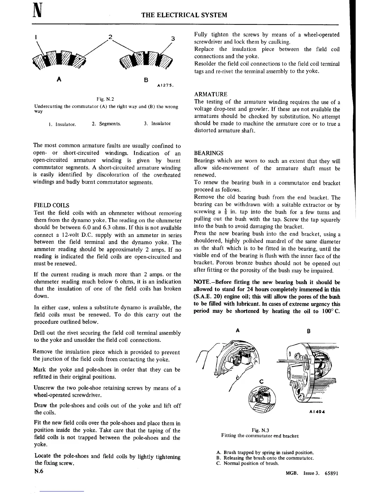
Fig.
N.2
Undercutting the
commutator
(A) the right
way
and (B) the
wrong
way
1. Insulator.
2. Segments.
3. Insulator
The
most
common
armature
faults
are
usually confined
to
open-
or
short-circuited
windings.
Indication
of
an
open-circuited
armature
winding
is
given
by burnt
commutator
segments.
A
short-circuited
armature
winding
is
easily identi■ed
by
discoloration of
the
overheated
windings
and badly burnt
commutator
segments.
FIELD COILS
Test the
■eld
coils with
an
ohmmeter
without
removing
them from
the dynamo
yoke. The
reading
on
the
ohmmeter
should be
between 6.0
and 6.3 ohms. If this
is
not
available
connect
a
12-volt D.C.
supply with
an
ammeter
in series
between the field
terminal
and
the
dynamo
yoke. The
ammeter
reading should
be
approximately
2
amps.
If
no
reading
is
indicated
the ■eld
coils
are
open-circuited
and
must
be
renewed.
If
the
current
reading
is
much
more
than
2
amps. or
the
ohmmeter reading much below 6
ohms,
it
is
an
indication
that the
insulation
of
one
of
the ■eld coils has broken
down.
In
either
case,
unless
a
substitute dynamo
is
available, the
field
coils
must
be renewed. To do
this
carry
out
the
procedure outlined below.
Drill
out
the
rivet securing
the field coil terminal
assembly
to
the yoke and unsolder the field coil
connections.
Remove
the
insulation
piece
which
is provided
to
prevent
the
junction of the ■eld
coils from
contacting
the
yoke.
Mark the
yoke and
pole-shoes
in
order that they
can
be
re■tted
in
their original
positions.
Unscrew the
two
pole-shoe
retaining
screws
by
means
of
a
wheel-operated
screwdriver.
Draw the
pole-shoes
and coils
out
of
the
yoke and lift off
the
coils.
Fit the
new
field
coils
over
the pole-shoes
and place them
in
position inside the
yoke. Take
care
that
the
taping
of the
■eld
coils
is
not
trapped between
the
pole-shoes
and the
yoke.
Locate the
pole-shoes
and ■eld
coils
by lightly
tightening
the ■xing
screw.
N.6
Fully tighten the
screws
by
means
of
a
wheel-operated
screwdriver
and
lock
them
by caulking.
Replace the insulation
piece between the field coil
connections
and
the
yoke.
Resolder the field coil
connections
to
the ■eld
coil
terminal
tags
and
re-rivet
the terminal
assembly
to
the yoke.
ARMATURE
The
testing
of the
armature
winding
requires
the
use
of
a
voltage
drop—test
and
growler. If
these
are
not
available
the
armatures
should
be checked
by
substitution.
No
attempt
should
be
made
to
machine
the
armature
core or
to true
a
distorted
armature
shaft.
BEARINGS
Bearings
which
are
worn
to
such
an
extent
that they
will
allow
side-movement
of
the
armature
shaft
must
be
renewed.
To
renew
the
bearing
bush
in
a
commutator
end bracket
proceed
as
follows.
Remove
the
old bearing
bush from
the end
bracket.
The
bearing
can
be
withdrawn
with
a
suitable
extractor
or
by
screwing
a
%
in.
tap
into
the
bush for
a
few
turns
and
pulling
out
the
bush
with the
tap.
Screw
the
tap
squarely
into
the bush
to
avoid damaging
the
bracket.
Press
the
new
bearing
bush
into
the
end bracket,
using
a
shouldered,
highly
polished
mandrel
of the
same
diameter
as
the
shaft
which
is
to
be ■tted
in
the
bearing,
until
the
visible
end of
the
bearing
is
■ush
with the
inner
face of
the
bracket.
Porous
bronze
bushes
should
not
be
opened
out
after ■tting
or
the
porosity
of
the bush
may
be
impaired.
NOTE—Before
fitting the
new
bearing bush
it should be
allowed
to
stand for
24
hours
completely
immersed
in
thin
(S.A.E. 20)
engine
oil; this
will allow the
pores
of
the bush
to
be
filled
with
lubricant.
In
cases
of
extreme
urgency
this
period
may
be shortened
by heating the
oil
to
100°
C.
Fig.
N.3
Fitting
the
commutator
end
bracket
A.
Brush
trapped by spring in raisedposition.
B. Releasingthe brush
onto
the
commutator.
C. Normal position of brush.
MGB.
Issue3. 65891