M
THE
BRAKING
SYSTEM
To
remove
the
wheel cylinder disconnect the brake ■uid
supply
pipe,
placing
a
container
to
catch the ■uid.
Withdraw the circlip
and
retaining
washer and
remove
the
cylinder.
Extract
the split
pin
and
withdraw the
clevis
pin
to
release
the hand
brake cable from the lever. Detach the rubber dust
cover
from the brake
lever
at
the
rear
of the backplate and
withdraw the
lever.
Withdraw the
tappets
from the spindle adjuster and
screw
the
adjusting spindle inwards until clear
of
the threads.
Remove the
two nuts
and
spring
washers from the
rear
of
the backplate
to
release
the
adjuster body.
Assembling
Thoroughly
clean
the adjuster body,
tappets,
and
adjuster.
Smear the adjuster threads and
tappets
with Lockheed
Expander Lubricant. Screw the adjuster fully home
and
slide the
tappets
into
the body,
ensuring
that
the tapered
portion
on
each
is
facing
inwards.
Examine the rubber seals
on
both
pistons
and
renew
them
should they
appear
damaged
or
distorted.
It
is
usually
advisable
to
renew
the rubbers when
rebuilding the
cylinders. Smear all internal
parts
with ■uid
and
reassemble. Replace the dust
covers.
Hold the cylinder
up
against
the backplate and replace the ■at
washer and
circlip.
Reconnect
the ■uid
supply
pipe.
Hold the brake lever
against
the backplate
and
replace
the
rubber
boot. Reconnect the
hand
brake cable.
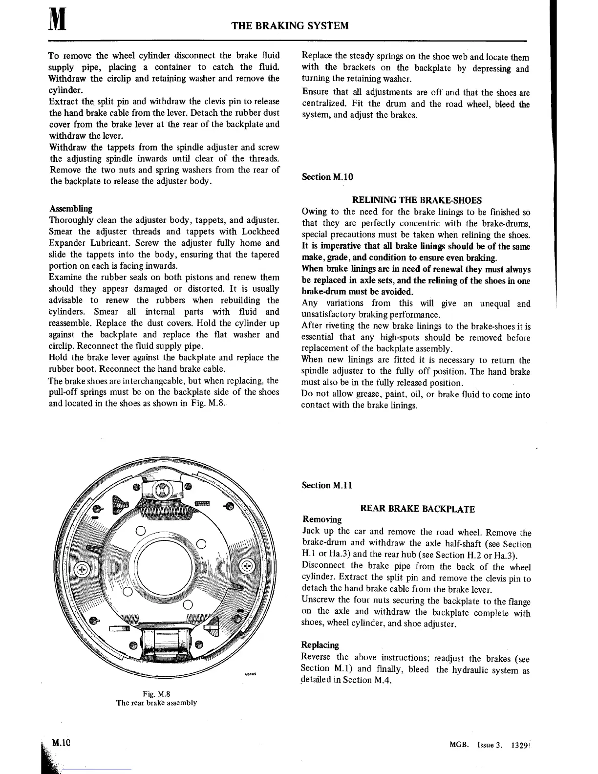
The brake shoes
are
interchangeable,
but when
replacing, the
pull-off
springs
must
be
on
the backplate side of the
shoes
and located
in
the shoes
as
shown
in
Fig.
M.8.
Fig. MS
The
rear
brake assembly
Replace
the
steady
springs
on
the
shoe
web
and locate
them
with
the
brackets
on
the
backplate
by
depressing
and
turning
the
retaining
washer.
Ensure
that
all adjustments
are
off
and that the
shoes
are
centralized.
Fit the
drum
and the
road wheel, bleed
the
system,
and
adjust the brakes.
Section
M. 10
RELINING
THE
BRAKE-SHOES
Owing
to
the need for
the brake
linings
to
be ■nished
so
that they
are
perfectly
concentric
with the brake-drums,
special
precautions
must
be taken
when relining the
shoes.
It
is imperative that
all brake linings
should
be
of
the
same
make,
grade, and
condition
to
ensure
even
braking.
When
brake linings
are
in
need of
renewal they
must
always
be replaced
in
axle
sets,
and the
re■ning
of the shoes
in
one
brake-drum
must
be avoided.
Any
variations
from
this
will
give
an
unequal and
unsatisfactory
braking
performance.
After
riveting
the
new
brake linings
to
the
brake-shoes
it is
essential that
any
high-spots
should
be
removed before
replacement
of
the backplate
assembly.
When
new
linings
are
fitted
it is
necessary
to return
the
spindle
adjuster
to
the fully
off
position.
The
hand
brake
must
also be
in
the fully
released
position.
-
Do
not
allow
grease,
paint,
oil,
or
brake
■uid
to
come
into
contact
with the
brake
linings.
Section
M.ll
REAR
BRAKE
BACKPLATE
Removing
Jack
up
the
car
and
remove
the
road
wheel.
Remove
the
brake-drum
and
withdraw
the
axle half-shaft
(see
Section
H.l
or
Ha.3)
and the
rear
hub (see
Section
H2
or
Ha.3).
Disconnect
the
brake
pipe
from
the
back
of the
wheel
cylinder.
Extract
the
split
pin
and
remove
the
clevis
pin
to
detach
the
hand
brake
cable
from
the brake
lever.
Unscrew
the
four
nuts
securing
the
backplate
to
the ■ange
on
the
axle
and
withdraw
the
backplate
complete
with
shoes,
wheel
cylinder,
and
shoe
adjuster.
Replacing
Reverse
the
above
instructions;
readjust
the
brakes (see
Section
MI)
and ■nally,
bleed
the
hydraulic
system
as
detailed
in
Section
M.4.
MGB.
Issue3.
1329i