A
THE ENGINE
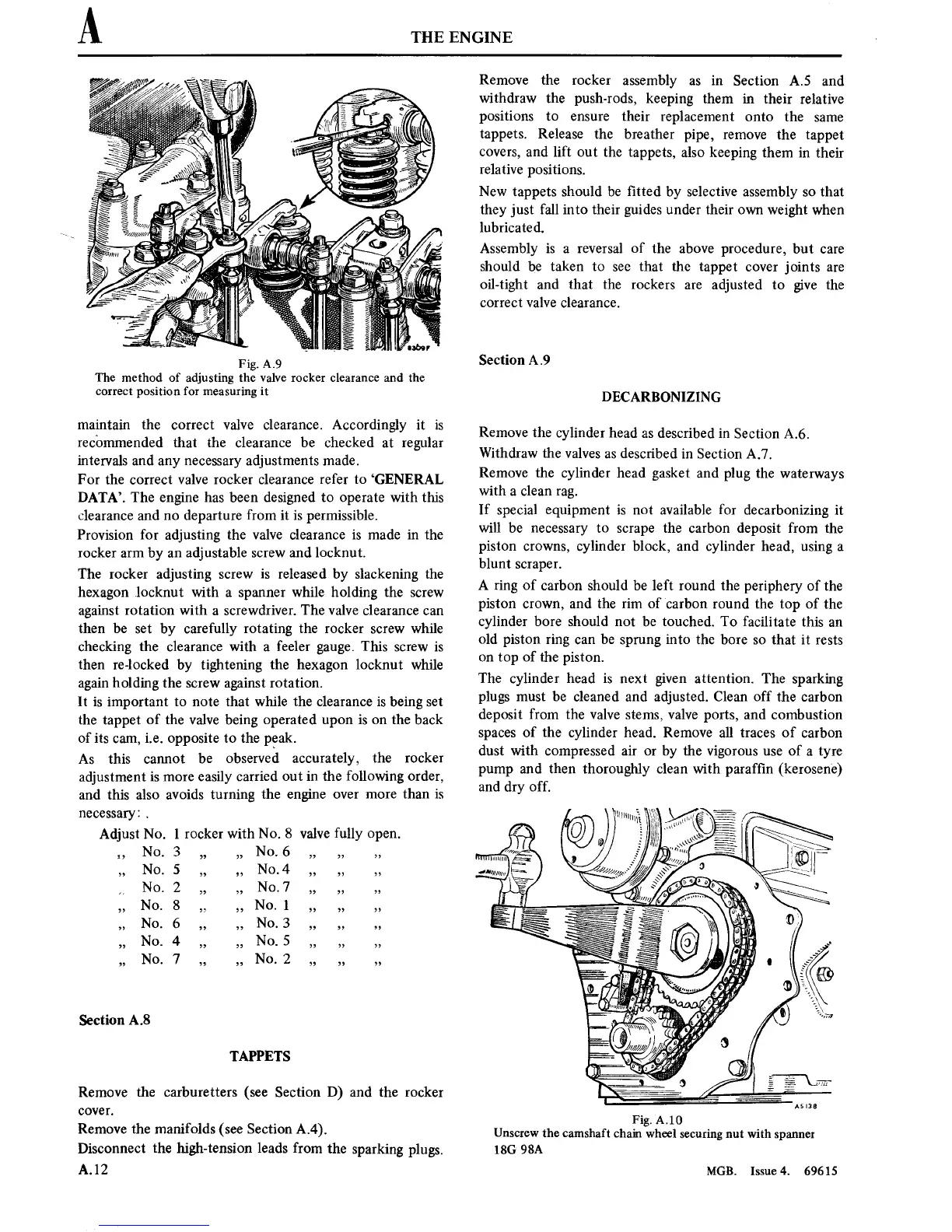
Fig. A.9
The method of adjusting
the valve rocker clearance and the
correct
position
for
measuringit
maintain
the
correct
valve clearance. Accordingly
it is
recommended
that the clearance be
checked
at
regular
intervals and
any
necessary
adjustments made.
For the
correct
valve rocker clearance
refer
to
‘GENERAL
DATA’.
The
engine
has been designed
to operate
with this
clearance and
no
departure
from
it is
permissible.
Provision
for adjusting the valve clearance
is
made
in
the
rocker
arm
by
an
adjustable
screw
and locknut.
The rocker
adjusting
screw
is
released by slackening the
hexagon
locknut with
a spanner
while holding the
screw
against rotation
with
a
screwdriver. The valve clearance
can
then be
set
by carefully
rotating
the rocker
screw
while
checking the clearance with
a
feeler
gauge.
This
screw
is
then re-locked by tightening
the
hexagon locknut while
again
holding the
screw
against rotation.
It is
important
to note
that while the clearance
is
being
set
the
tappet
of the valve
being
operated
upon
is
on
the back
of
its
cam,
i.e.
opposite
to
the
peak.
As
this
cannot
be observed
accurately,
the
rocker
adjustment is
more
easily carried
out
in
the following order,
and
this also avoids
turning
the
engine
over
more
than
is
necessary:
.
Adjust No.
l
rocker with No. 8
valve fully
open.
1’
NO' 3
9’ ”
NO' 6
’9
’3 ’7
”
NO’ 5
”
”
NO' 4
’9 3’ 35
NO' 2
7’ ’7
No' 7
” 9’
’3
’3
No‘
8
5
3’
No‘
1
’9
’, 77
H
NO' 6
” 77
No'
3
’9 ” 5’
’9
NO'
4
’9 9’
No' 5
’5 ’9 ’7
”
No' 7
” 5’
NO‘
2
9’ I, 9’
Section
A.8
TAPPETS
Remove
the carburetters
(see
Section
D)
and the rocker
cover.
Remove
the manifolds (see
Section A.4).
Disconnect
the high-tension leads from
the
sparking
plugs.
A.12
Remove
the rocker
assembly
as
in Section A.5 and
withdraw the push-rods,
keeping them
in
their
relative
positions
to
ensure
their
replacement
onto
the
same
tappets.
Release
the breather
pipe,
remove
the
tappet
covers,
and lift
out
the
tappets,
also
keeping them
in
their
relative
positions.
New
tappets
should
be
■tted
by selective assembly
so
that
they
just
fall
into
their guides under their
own
weight when
lubricated.
Assembly
is
a
reversal
of the
above procedure,
but
care
should
be
taken
to
see
that
the
tappet
cover
joints
are
oil-tight and that the rockers
are
adjusted
to
give
the
correct
valve clearance.
Section
A.9
DECARBONIZING
Remove the cylinder
head
as
described
in
Section
A.6.
Withdraw the
valves
as
described
in
Section
A.7.
Remove
the
cylinder head gasket and plug
the
waterways
with
a
clean
rag.
If special
equipment is
not
available
for
decarbonizing
it
will be
necessary
to
scrape
the carbon deposit from
the
piston
crowns,
cylinder
block, and cylinder head,
using
a
blunt
scraper.
A
ring
of carbon should
be
left
round the periphery of
the
piston
crown,
and the
rim
of
carbon round the
top
of
the
cylinder bore should
not
be touched.
To
facilitate
this
an
old
piston ring
can
be
sprung
into
the
bore
so
that
it
rests
on
top
of
the
piston.
The cylinder head
is
next
given attention.
The sparking
plugs
must
be cleaned and adjusted.
Clean
off
the carbon
deposit from the
valve
stems,
valve
ports,
and combustion
spaces
of the
cylinder
head.
Remove all
traces
of
carbon
dust with
compressed
air
or
by the
vigorous
use
of
a
tyre
pump
and
then thoroughly
clean with paraf■n
(kerosene)
and dry off.
m
_
\
i
_.
,W
_
“iv
lillu‘u
(A
muumi
H
as
Q)
(0
‘
l”
\
/
1‘
\\\\\\\‘
z:
\-
2
.5
-
"■rm
:■
\
~
,
'
.3
////////{g6.~‘/
\\\\\
S
w
mum
“
Fig.
A
.
10
Unscrew
the camshaft
chain wheel
securing
nut
with
spanner
18G
98A
MGB.
Issue
4. 69615