THE
OVERDRIVE (TYPE L.H.)
2
6
J
.i,v. . ...__
n-maln»
lg-q..-
.-———].._
00988
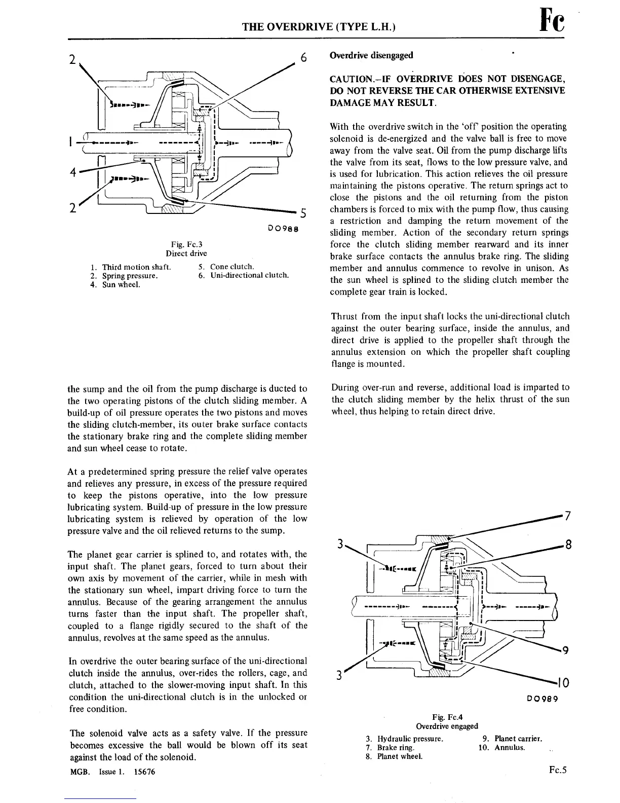
Fig.
Fc.3
Direct
drive
1.
Third motion
shaft.
2. Spring
pressure.
4.
Sun
wheel.
5. Cone
clutch.
6.
Uni-directional
clutch.
the
sump
and the oil
from the
pump
discharge
is
ducted
to
the
two
operating
pistons
of the
clutch sliding
member. A
build-up
of oil
pressure
operates
the
two
pistons
and
moves
the sliding
clutch-member,
its
outer
brake surface
contacts
the
stationary
brake
ring
and
the complete sliding member
and
sun
wheel
cease
to
rotate.
At
a
predetermined
spring
pressure
the relief valve
operates
and relieves
any
pressure,
in
excess
of the
pressure
required
to
keep
the
pistons
operative, into
the low
pressure
lubricating
system.
Build-up
of
pressure
in
the low
pressure
lubricating
system
is
relieved by
operation
of
the low
pressure
valve and the oil
relieved
returns to
the
sump.
The
planet
gear
carrier is
splined
to,
and
rotates
with,
the
input
shaft. The
planet
gears,
forced
to turn
about
their
own
axis
by
movement
of the
carrier,
while
in
mesh with
the
stationary
sun
wheel,
impart
driving
force
to
turn
the
annulus.
Because
of the
gearing
arrangement
the annulus
turns
faster than the
input
shaft. The propeller
shaft,
coupled
to
a
■ange
rigidly secured
to
the shaft of
the
annulus, revolves
at
the
same
speed
as
the annulus.
In overdrive
the
outer
bearing
surface of the
uni-directional
clutch inside the
annulus, over-rides the rollers,
cage,
and
clutch,
attached
to
the slower-moving
input
shaft.
In
this
condition the
uni-directional clutch
is in
the unlocked
or
free
condition.
The solenoid valve
acts
as a
safety
valve.
If the
pressure
becomes
excessive
the ball
would
be
blown
off
its
seat
against
the load of the solenoid.
MGB.
Issue
1. 15676
Fe
Overdrive disengaged
'
CAUTION—IF
OVERDRIVE
DOES
NOT DISENGAGE,
DO NOT REVERSE THE CAR
OTHERWISE EXTENSIVE
DAMAGE MAY RESULT.
With the overdrive switch
in
the ‘off’
position
the
operating
solenoid
is
de-energized and
the valve ball
is
free
to
move
away
from the valve
seat.
Oil
from the
pump
discharge
lifts
the
valve
from
its
seat,
■ows
to
the low
pressure
valve, and
is
used for lubrication. This
action
relieves the oil
pressure
maintaining
the
pistons operative.
The
return
springs
act to
close
the
pistons
and the oil
returning
from the
piston
chambers
is
forced
to
mix
with
the
pump
flow, thus
causing
a
restriction
and damping the
return movement
of the
sliding
member. Action
of the secondary
return
springs
force the clutch sliding member rearward and
its inner
brake
surface
contacts
the annulus brake
ring.
The
sliding
member
and annulus
commence
to
revolve
in unison.
As
the
sun
wheel
is
splined
to
the sliding clutch
member
the
complete
gear
train is
locked.
Thrust from the
input
shaft
locks
the uni-directional clutch
against
the
outer
bearing
surface,
inside
the annulus, and
direct drive
is
applied
to
the propeller shaft
through
the
annulus
extension
on
which the propeller
shaft coupling
flange
is
mounted.
During
over-run
and
reverse,
additional load
is
imparted
to
the
clutch
sliding member by
the helix thrust
of the
sun
wheel, thus helping
to
retain
direct drive.
Fig. Fc.4
Overdrive
engaged
3. Hydraulic
pressure.
7.
Brake ring.
8.
Planetwheel.
9. Planetcarrier.
10. Annulus.
Fc.5