Appendix: Dielectric Material
AC393 Application Note Revision 14.0 93
8 Appendix: Dielectric Material
The impedance of the traces depends on the geometry of the traces and the dielectric material used. The
skew of the signal depends on the dielectric constant and loss of signal strength depends on the loss
tangent of the material. The SmartFusion2 Development Kit board uses Nelco 4000-13 dielectric
material. However, selection of the material is made based on the speed and length of the high-speed
traces. Simulations are recommended on high-speed serial links to converge on the type of the material
used.
If the total trace length is less than 20 inches with a speed at or below 3.125 Gbps, FR-4 may be
acceptable. Another design option is to use low-loss dielectric PCB material, such as Rogers 4350,
GETEK, or ARLON. It can provide increased eye-opening performance when longer trace
interconnections are required. If longer traces or faster speed are required, consider using a high-speed
material such as ROGERS 3450.
While designing for gigabit serial links, the weaving structure of PCB dielectric material should be taken
into consideration. A PCB dielectric substrate is constructed from woven fiberglass fabrics strengthened
and bound together with epoxy resin.
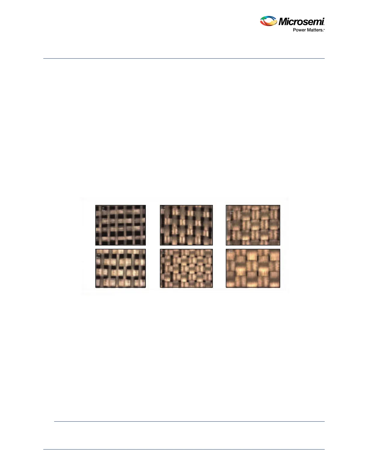
A typical weaving is shown in the following figure.
Figure 89 • Fiberglass Weaving
1
Depending on the density of weaving, the PCB materials are numbered as 106, 1080, 2113, 2116, 1652,
and 7268. Trace routed on the PCB is non-homogeneity in dielectric constant due to weaving. This
causes discontinuities in the trace impedance, which results in improper eye-opening at the receiving
end. For further reading, refer to the Solving PCB Fiber Weave Issues.
1. signal-integrity.tm.agilent.com/2011/pcb-fiber-weave
106
1080
2113
2116
1652
7268