Board Design Guidelines for SmartFusion2 SoC and IGLOO2 FPGAs
AC393 Application Note Revision 14.0 32
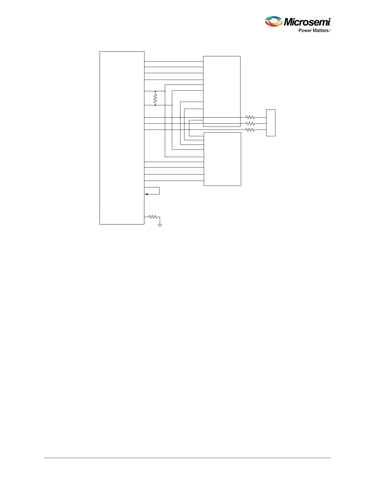
Figure 18 • DDR2 Interface
With short traces, the address, control, and command signals may not require both parallel (RT) and
series (RS) termination. In a worst-case scenario, a small series resistor (RS) of about 10 Ω or less is
required. This series termination is not used for impedance matching, but for dampening the signals.
Note: To get length matching, short the TMATCH_OUT to TMATCH_IN with the shortest loop.
Note: Short ECC_TMATCH_ OUT and ECC_TMATCH_ IN when using ECC bits.
2.9.5 DDR3 Guidelines
The following are the guidelines for connecting to the DDR3 memory:
• DDR3 data nets have dynamic on-die termination (ODT) built into the controller and SDRAM. The
configurations are 40 Ω, 60 Ω, and 140 Ω. VTT pull-up is not necessary.
• Characteristic impedance: Zo is typically 50 Ω, and Zdiff (differential) is 100 Ω.
DDR3 interfacing with SmartFusion2/IGLOO2 devices for 8-bit and 16-bit interfaces is shown in
Figure 19, page 33 and Figure 20, page 33.
SmartFusion2/IGLOO2
DDR 2 SDRAM
x16- bit
DDR2 SDRAM
x16- bit
xDDR_CLK
xDDR_CLK_N
Contr ol Lines
CKE, CS, WE, RAS, CAS
Address Lines [13:0]
xDDR_DQ [15:0]
Bank Address [2:0]
xDDR_DM_RDQS [1:0]
xDDR_DQ [31:16]
xDDR_DM_RDQS [3:2]
xDDR_DQS [3:2]
xDDR_DQS [1:0]_N
100
VTT
Rt
xDDR_TMATCH_OUT
xDDR_TMATCH_IN
xDDR_TMATCH_ECC_OUT
xDDR_TMATCH_ECC_IN
xDDR_IMP_CALIB_ECC
240Ω_1%
xDDR_DQS [1:0]
xDDR_DQS [3:2]_N