Creating Schematic Symbols Using Cadence OrCAD Capture CIS for SmartFusion2
and IGLOO2 Designs
AC393 Application Note Revision 14.0 75
8. Double-click the part that is created to display the first section as shown in the following figure.
Figure 74 • Schematic Symbol - First Section
9. You can navigate to all the sections that are created.
• To go to the next part, go to View > Next Part or press Ctrl + N.
• To go to the previous part, go to View > Previous Part or press Ctrl + B.
• To see all the blocks of the schematic symbol, go to View > Package.
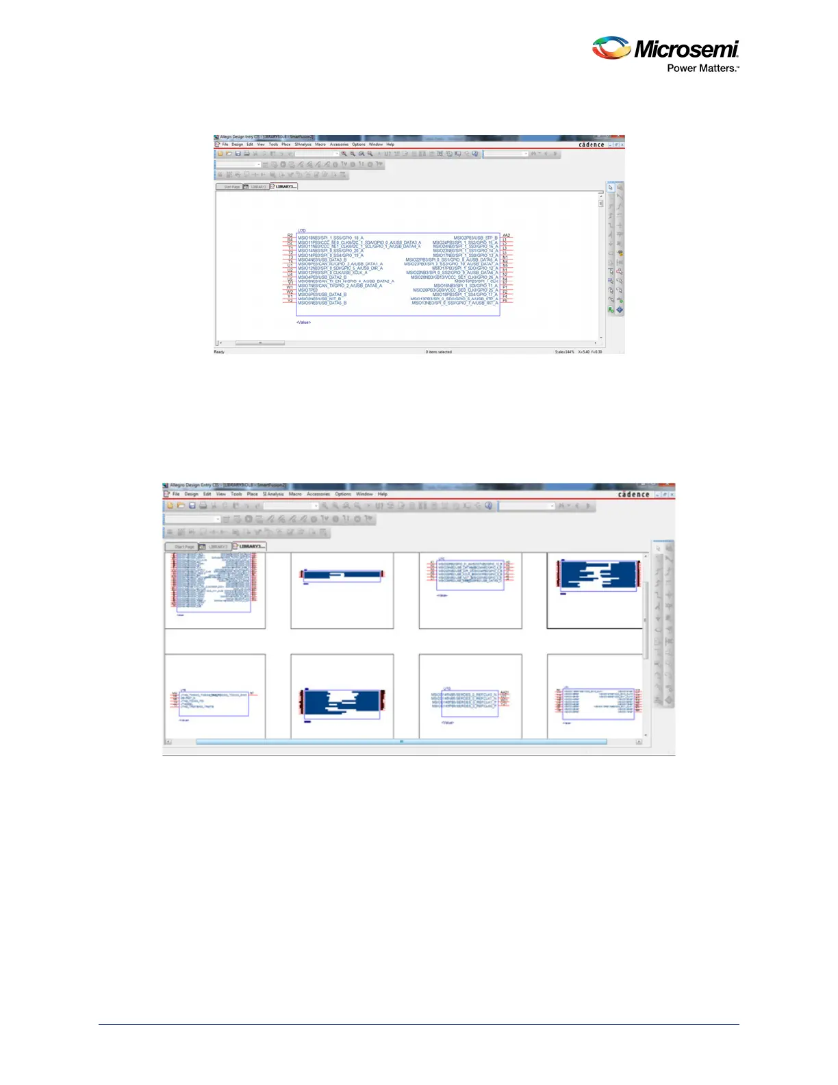
The schematic symbol is ready to use. The following figure shows all the blocks of the schematic symbol
that are generated from the Example PAT spreadsheet.
Figure 75 • Package View of the Schematic Symbol