Board Design Guidelines for SmartFusion2 SoC and IGLOO2 FPGAs
AC393 Application Note Revision 14.0 26
2.7.3 SPI Slave Programming
The following figure shows the SmartFusion2/IGLOO2 SPI slave programming configuration when an
external processor is the master.
Figure 13 • SPI Slave Programming by External Microprocessor
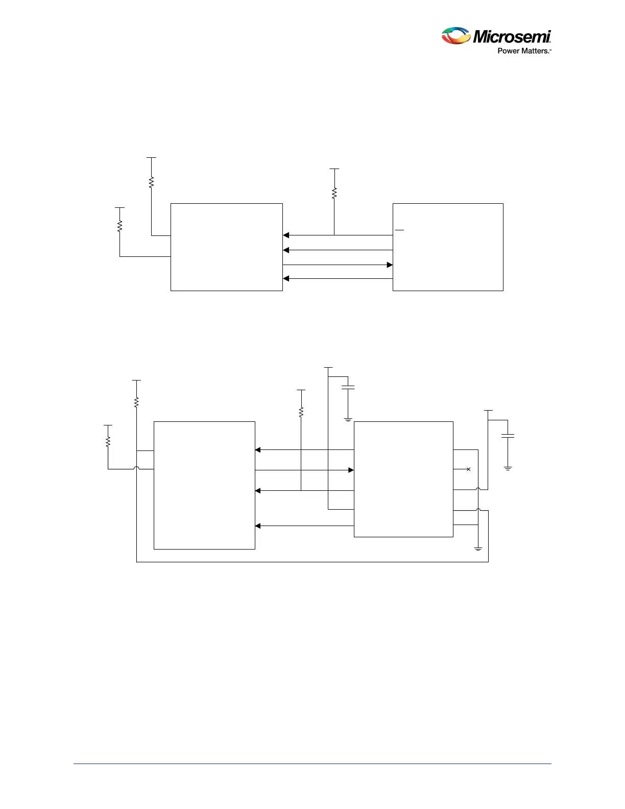
The following figure shows the SmartFusion2/IGLOO2 SPI slave programming configuration when an
external programmer is the master.
Figure 14 • SPI Slave Programming by External Programmer
2.8 SerDes
SmartFusion2/IGLOO2 SerDes I/O reside in dedicated I/O banks. The number of SerDes I/O depends
on the device size and pin count. For example, the M2S050T/M2GL050T device has two SerDes blocks
(SERDES0 and SERDES1), which reside in bank 6 and bank 9 out of 10 I/O banks. The
M2S010T/M2GL010T device has a single SerDes block (SERDES0), which resides in I/O bank 5.
SC_SPI_CLK
SC_SPI_SDO
SC_SPI_SS
SC_SPI_SDI
External Microprocessor
SPI Master
CS
SCLK
MISO
10 K
VDDIx
SmartFusion2/IGLOO2
(SPI Slave)
10 K
VDDIy
y = Bank number where the pin is located
VPP
10 K
FLASH_GOLDEN_N
DEVRST_N
MOSI
SC_SPI_CLK
SC_SPI_SDO
SC_SPI_SS
SC_SPI_SDI
FlashPro5 Header
SCK
MISO
SS
VPUMP
MOSI
GND
PROG_MODE
VSPI
FL_GLDN
GND
VPP
VDDIx
0.1
μ
F
Mfr. P/N: HTST-105-01-L-DV-A
Mfr.: Samtec Inc
0.1
μ
F
1
3
5
7
9
10
8
6
4
2
10 K
VDDIx
SmartFusion2/IGLOO2
(SPI Slave)
10 K
VDDIy
y = Bank number where the pin is located
VPP
10 K
FLASH_GOLDEN_N
DEVRST_N
 Loading...