Layout Guidelines for SmartFusion2- and IGLOO2-Based Board Design
AC393 Application Note Revision 14.0 41
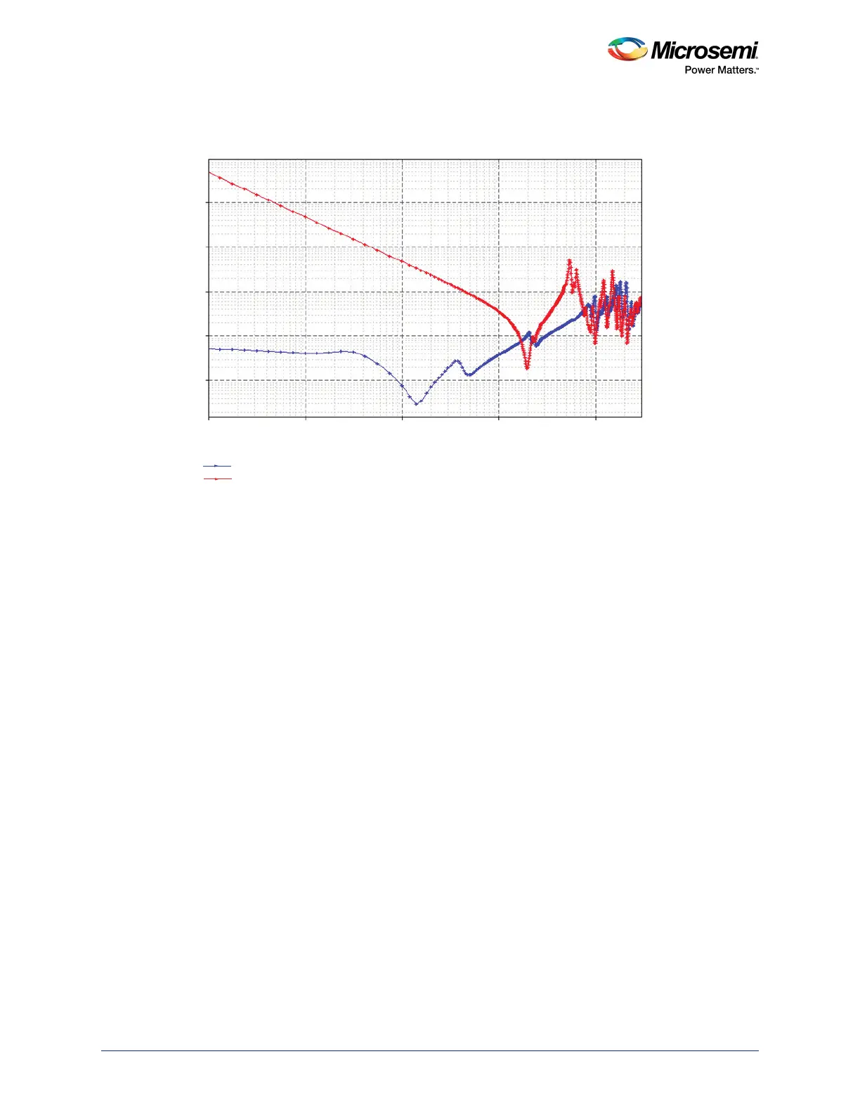
Figure 27 • Impedance Profile of VDD Plane with Respect to Frequency
3.3 SerDes
PCB designers often overlook the requirement of isolating the noise generated by the digital components
with the SerDes high-speed designs. It is necessary to provide a low-noise supply for the sensitive
analog portions of the SerDes devices. Noise due to various power supply voltages can be coupled into
the analog portion of the chip and may produce unwanted fluctuations in the sensitive stages of the
device. The performance of SerDes highly depends on robust layout techniques. This section discusses
the layout guidelines for power supply for the SerDes and the SerDes PLL.
3.3.1 Component Placement
3.3.1.1 Core Power (SERDES_x_VDD)
• All decoupling capacitors (0.1 µF and 0.01 µF) are placed on the pad adjacent to the BGA via of the
corresponding pin, as shown in Figure 25, page 40. The capacitor pad to via trace should be as
small as possible. At least one 0.1 µF and one 0.01 µF capacitors should be placed for each SerDes
bank.
• The bypass capacitor (10 µF) should be placed at the edge of the integrated circuit (IC).
3.3.1.2 SerDes I/O Power (SERDES_x_VDDAIO)
• All decoupling capacitors (0.1 µF and 0.01 µF) are placed on the pad adjacent to the BGA via of the
corresponding pin, as shown in Figure 24, page 39. At least one of the capacitors (0.1 µF and 0.01
µF) should be placed for each SerDes bank. The capacitor pad to via trace should be as small as
possible.
• The bypass capacitor (10 µF) should be placed at the edge of the IC.
Z Amplitude (Ω)
Frequency (GHz)
VDD Plane with Decoupling Capacitors
VDD Plane without Decoupling Capacitors
100
10
1
0.1
0.01
1e-4 2e-4 1e-3 2e-3 0.01 0.02 0.1 0.2 0.3 1 2 3
 Loading...