Layout Guidelines for SmartFusion2- and IGLOO2-Based Board Design
AC393 Application Note Revision 14.0 53
3.6.3 Simulations
The target impedance of the VDDIO1 plane is calculated as 330 mΩ based on the following values
(see Power Supply, page 38):
•V
SUPPLY
= 3.3 V,
•I
trans
= 500 mA
• Ripple = 5%
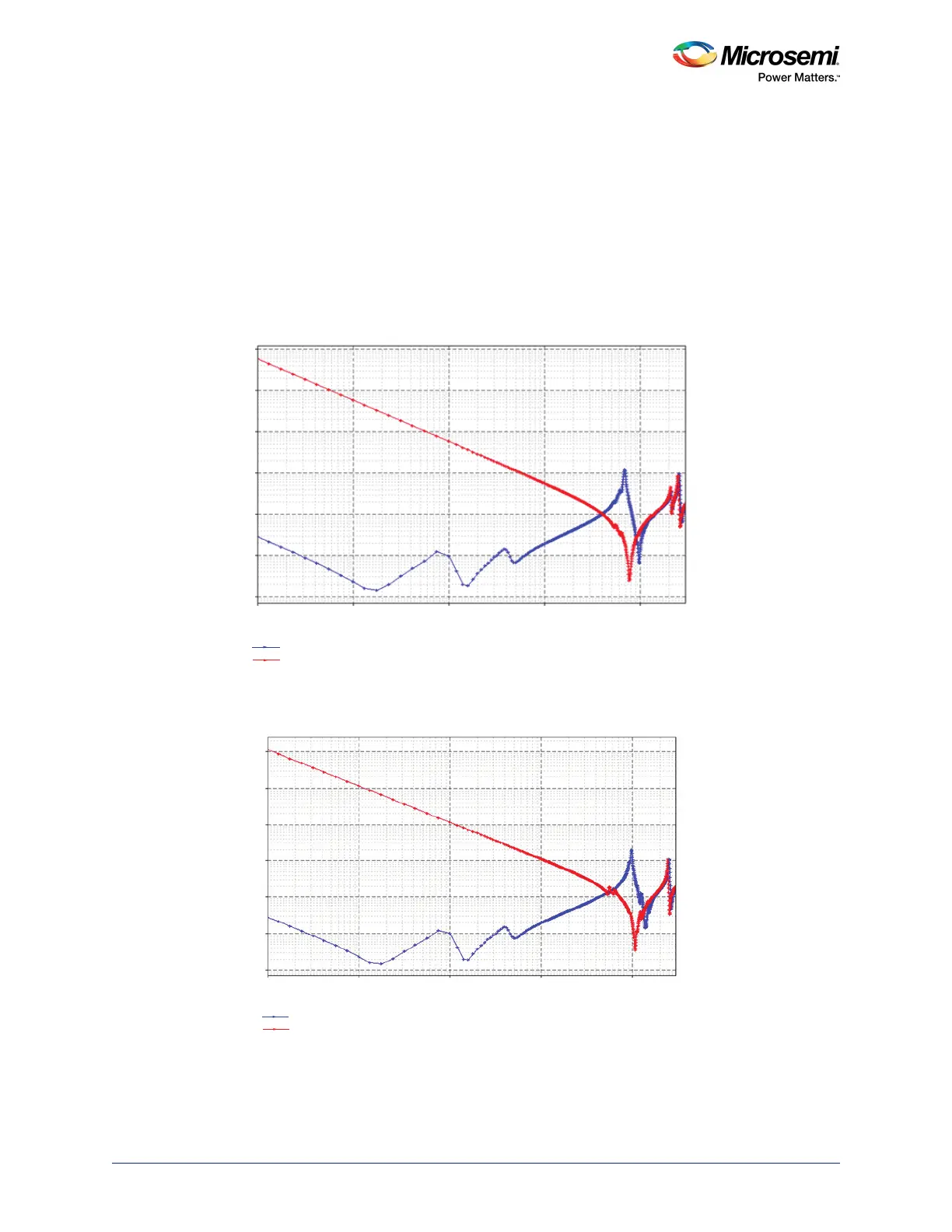
The following figures show the impedance of the planes (VDDIO1 and VDDIO2). The impedance of the
plane has been improved by decoupling capacitors and is kept under 0.2 Ω till 100 MHz.
Figure 44 • Impedance Profile of VDDIO1 Plane Over Frequency Range
Figure 45 • Impedance Profile of VDDIO2 Plane Over Frequency Range
Z Amplitude (Ω)
Frequency (GHz)
Impedance of VDDIO1 with Decoupling Capacitors
Impedance of VDDIO1 without Decoupling Capacitors
1e3
1e4
100
10
1
0.1
1e-4 2e-4 1e-3 2e-3 0.01 0.02 0.1 0.2 0.3 1 2 3
0.01
Z Amplitude (Ω)
Frequency (GHz)
Impedance of VDDIO2 with Decoupling Capacitors
Impedance of VDDIO2 without Decoupling Capacitors
1e3
1e4
100
10
1
0.1
1e-4 2e-4 1e-3 2e-3 0.01 0.02 0.1 0.2 0.3 1 2 3
0.01