Layout Guidelines for SmartFusion2- and IGLOO2-Based Board Design
AC393 Application Note Revision 14.0 60
• PCB: S-parameter model of SmartFusion2 Development Kit SerDes Traces
• RX_PRIMARY: S-parameter model of either the connector or the IBIS model of the receiver IC
device
Once all the model files are imported into the topology, the default configuration in the AMI model should
be left to calculate the appropriate coefficients by the tool and then to run the simulations.
Figure 56 • Typical Topology for SLA Simulation
3.9.3 Step 3: Configuration of AMI Model
The following configurations on the AMI model are required before simulating the serial channel:
3.9.3.1 TX AMI Model
The following figure shows the block diagram of the 3-tap Feed Forward equalizer structure for TX. The
output of the TX is given by the transfer function t
n-1
+ t
n
Z
-1
+ t
n+1
Z
-2
. The TX output depends on the
value of tap coefficients.
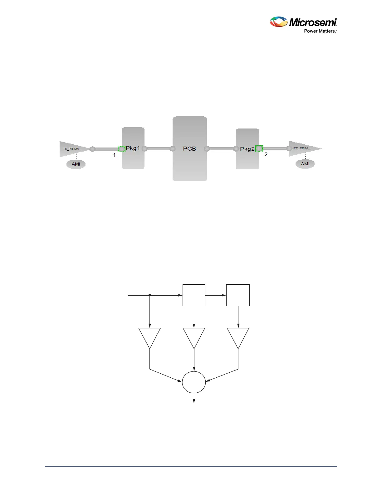
Figure 57 • Block Diagram of the 3-tap Feed Forward Equalizer
The following are the details of coefficients:
• t0: Pre-cursor tap setting. The range is from -0.4 to -0.01, default value is -0.01.
• t1: Main tap. The range is from 0.1 to 1, default value is 1.
in
pre-tap post-tap
z
-1
t
n
+
out
t
n-1
t
n+1
z
-1
 Loading...