Creating Schematic Symbols Using Cadence OrCAD Capture CIS for SmartFusion2
and IGLOO2 Designs
AC393 Application Note Revision 14.0 81
The default shape for most of the FPGA symbol pins is the LINE.
10. Leave the Pin Group column blank.
11. In the Position column, enter one of the following positions according to the requirement:
•Bottom
• Left
• Right
•Top
12. In the Section column, enter either a number or an alphabet based on the selection made for the
Part Numbering option. OrCAD Capture supports two Part Numbering options, that is, 1, 2, 3, 4,…
for Numeric option and A, B, C, D… for Alphabetical option.
13. Save the Excel file with an appropriate name.
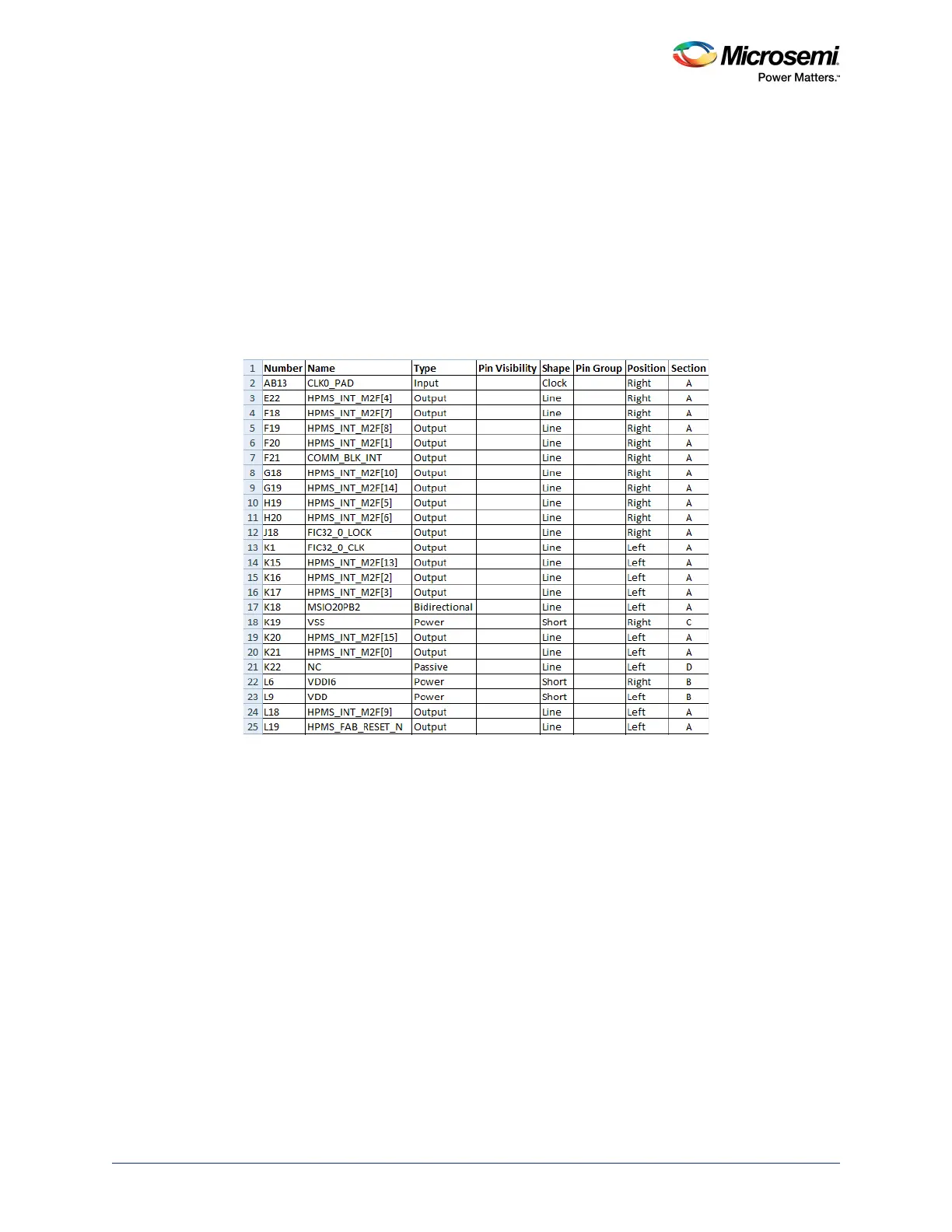
The following figure shows the final pin assignment spreadsheet.
Figure 85 • Final Example Spreadsheet to be Imported into OrCAD Capture
4.2.3 Generating a Capture Schematic Symbol
See Generating a OrCAD Capture Schematic Symbol, page 72“.