Board Design Guidelines for SmartFusion2 SoC and IGLOO2 FPGAs
AC393 Application Note Revision 14.0 7
Ceramic capacitors are preferred for high-frequency noise elimination and tantalum capacitors for low-
frequency noise elimination.
• For values ranging from 1 nF to 100 µF, use X7R or X5R (dielectric material) type capacitors.
• For values ranging from 100 µF to 1000 µF, use tantalum capacitors.
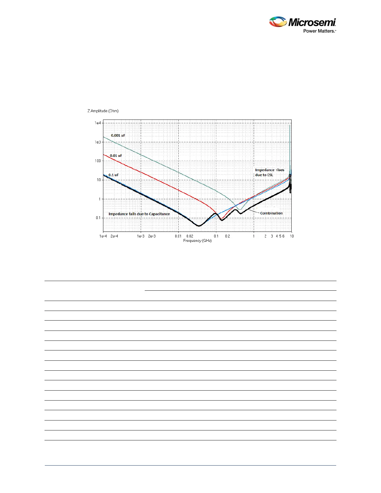
The following figure shows an impedance versus frequency graph for effective combinations of three
values of capacitors. From the graph it is evident that impedance is less for wider frequency band when
different capacitors are in parallel.
Figure 2 • Impedance of Three Capacitors in Parallel
The following table lists the recommended number of PCB decoupling capacitors for an
M2S050T/M2GL050T-FG896 device.
Table 2 • Power Supply Decoupling Capacitors
Pin Name
Number
of Pins
Ceramic Caps Tantalum Caps
0.01 µF 0.1 µF 10 µF 33 µF 22 µF 47 µF 100 µF 220 µF
1
330 µF
VDD 24 12 12 1 3 1
VDDI0 29 14 14 2
VDDI1 4 2 2 1
VDDI2 4 2 2 1
VDDI3 5 2 3 1
VDDI4 3 2 1 1
VDDI5 29 14 14 2
VDDI6 1 1 1
VDDI7 6 3 3 1
VDDI8 5 2 3 1
VDDI9 1 1 1
VPP 4 2 2 1
VREF0 3 2 1 1
VREF5 3 2 1 1