Creating Schematic Symbols Using Cadence OrCAD Capture CIS for SmartFusion2
and IGLOO2 Designs
AC393 Application Note Revision 14.0 70
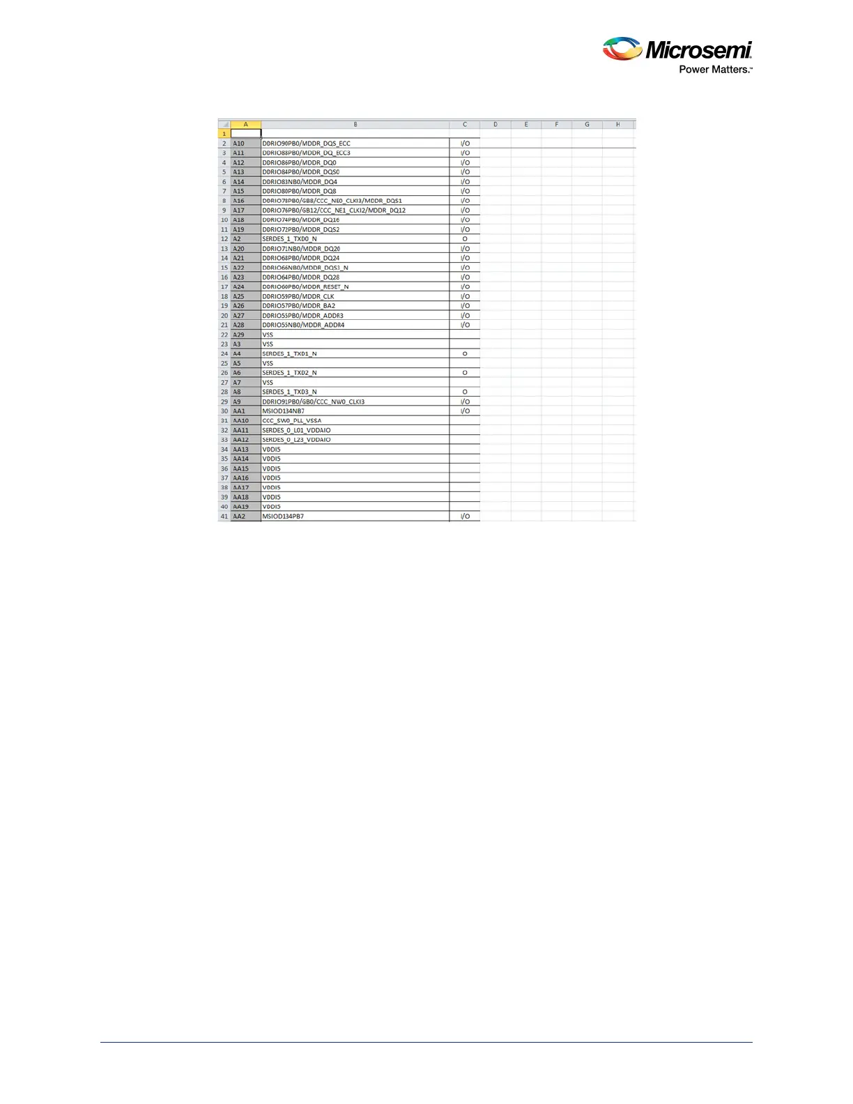
Figure 68 • Example PAT Spreadsheet - Editing Stage
6. Add the following headings for the columns. See Figure 69, page 71:
• Number
•Name
• Type
• Pin Visibility
• Shape
• Pin Group
• Position
• Section
For Type, Shape, Position, and Section columns, enter the information manually to avoid warnings from
the OrCAD Capture tool.
7. For Type column, choose and type one of the following options:
• Replace I with Input
• Replace O with Output
• Replace I/O with Bidirectional
Other pin types for the remaining pins:
• 3-State
• Open Collector
• Open Emitter
• Passive (Unused pins like DNC or NC)
• Power (Supply and ground pins)
8. Leave the Pin Visibility column blank. The check boxes are automatically populated in the New
Part Creation dialog in the OrCAD Capture tool. See Figure 72, page 74.
9. In the Shape column, enter one of the following shapes according to the requirement:
• Clock
•Dot
• Dot-Clock
•Line
• Short Clock