Creating Schematic Symbols Using Cadence OrCAD Capture CIS for SmartFusion2
and IGLOO2 Designs
AC393 Application Note Revision 14.0 80
5. Retain the columns A, B, F and delete the remaining columns as they are not required for generating
schematic symbols.
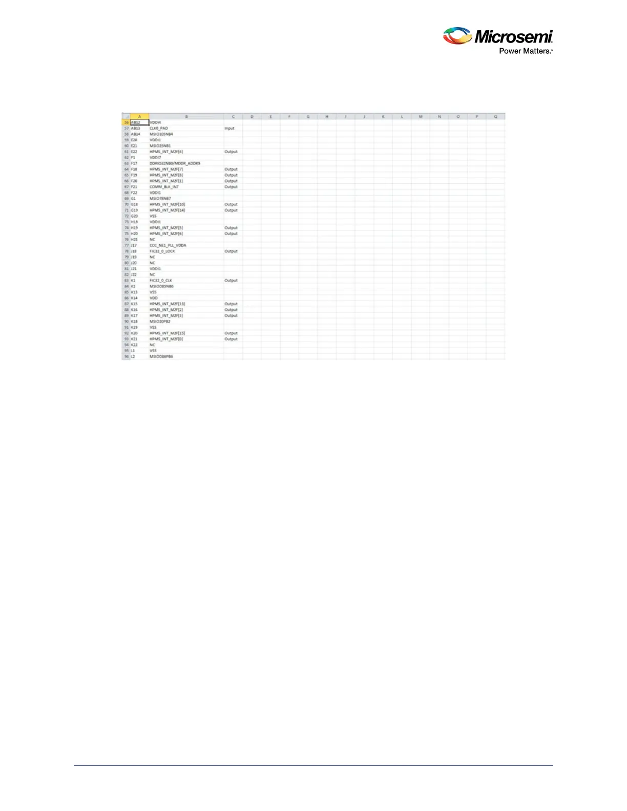
Figure 84 • Spreadsheet with the Pin Names Imported
6. Add the following headings for the columns. See Figure 85, page 81.
• Number
•Name
• Type
• Pin Visibility
• Shape
• Pin Group
• Position
• Section
By default Number, Name and Type columns are populated from the report.For Type, Shape, Position,
and Section columns, add information manually to avoid warnings from the OrCAD Capture tool.
7. For Type column, choose and type one of the following options:
• 3-State
• Bidirectional
• Input
• Open Collector
• Open Emitter
• Output
• Passive (Unused pins like DNC or NC)
• Power (Supply and ground pins)
8. Leave the Pin Visibility column blank. The check boxes are automatically populated in the New
Part Creation dialog.
9. In the Shape column, enter one of the following shapes according to the requirement:
• Clock
•Dot
• Dot-Clock
•Line
• Short Clock
• Short Dot
• Short Dot clock
• Short
• Zero Length