Layout Guidelines for SmartFusion2- and IGLOO2-Based Board Design
AC393 Application Note Revision 14.0 66
3.10.3.1.2 PCB Trace Models
The PCB file needs to be converted into a compatible format of simulator software. For example, .HYP
file format of PCB is required to simulate in Hyperlynx and SPD file format of PCB is required to simulate
in Sigrity. Once the PCB file is loaded in the simulation tool, check the stack-up that matches the PCB
stack-up and define the dielectric constant, Dk and dissipation factor, and Df of PCB material. The tool
extracts wrong models, if the above points not defined properly. Some tools run the simulations on PCB
file itself like Hyperlynx and some tools need S-parameter files of DDR3 traces to continue the
simulations. To extract S-parameter models of PCB traces assign the ports on both sides of the traces
and extract the S-parameter models of traces.
The following tools can be used to extract S-parameter models of PCB traces:
• Agilents ADS
• Mentors Hyperlynx
• Sigritys PowerSI
It is not mandatory to use above tools, there are many tools available in the market which can extract S-
parameter models.
3.10.3.2 Step 2: Creating Simulation Topology
These blocks are taken from the Sigrity tool. Topology is the same in any tools. The simulation can be
done in any tool, which supports DDR3 simulation.
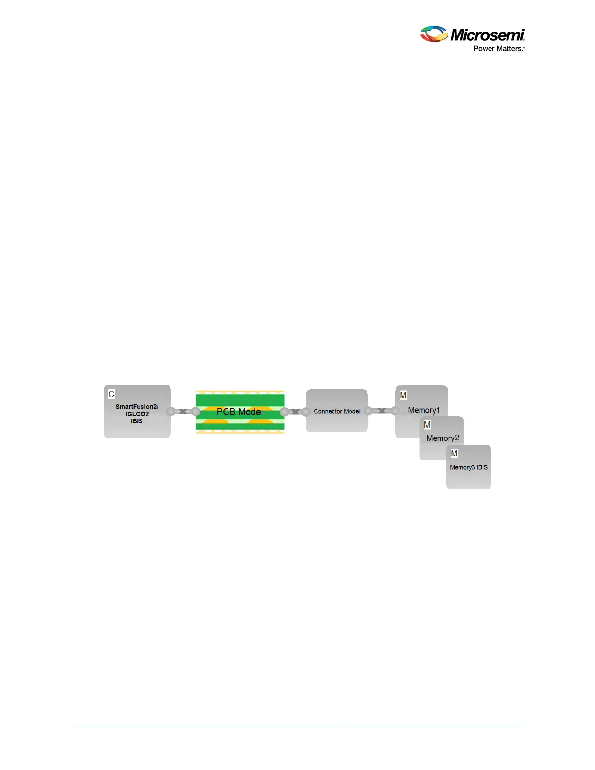
The following figure shows the typical topology blocks involved in the DDR3 simulations.
• SmartFusion2/IGLOO2 IBIS: IBIS model of SmartFusion2/IGLOO2
• PCB: S-parameter model of PCB file, connector models and DIMM PCB models
• Connector model: Spice models of connector
• Memory IBIS: IBIS models of DDR3 memory
Figure 63 • DDR3 Simulation Topology
3.10.3.3 Step 3: Simulation Setup
• Assign IBIS models to SmartFusion2/IGLOO2 and memory
• Assign connector model if used
• Assign the models for on board termination resistors
• Identify the DDR3 nets and classify according to data, control and address bus
• Keep the appropriate ODT for SF2 and memory.
• Keep the 40 to 60 Ω ODT for data and 80 to 120 Ω for DQS
• Set the maximum frequency at which the system will operate. For SF2 its 333 MHz
3.10.3.4 Step 4: Results
Observe the following results:
• Setup and hold time between data signals and the respective DQS over all corners.
• Setup and hold time between Control/Command/Address signals and the clock over all corners.
• Overshoot and undershoot of all signals with respect to JEDEC specifications over all corners, and
also DC threshold multi crossing that is due to the excessive ringing.