Board Design Guidelines for SmartFusion2 SoC and IGLOO2 FPGAs
AC393 Application Note Revision 14.0 20
The following table lists the output frequency range of the main crystal oscillator with different possible
sources.
The main crystal oscillator is operated in medium gain mode when a ceramic resonator is connected
between the XTLOSC_[MAIN/AUX]_EXTAL and XTLOSC_[MAIN/AUX]_XTAL pins.
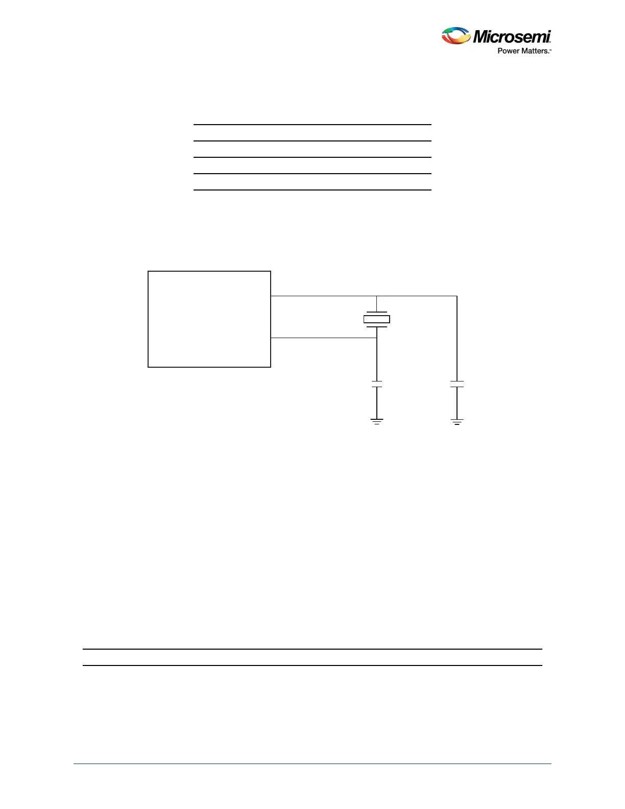
When a crystal is used, the load capacitance is determined by the external capacitors C
1
and C
2
, internal
capacitance, and stray capacitance (C
S
), as shown in the following figure.
Figure 5 • Crystal Oscillator
Typically, designers choose the values of capacitors C
1
and C
2
to match the crystal’s capacitance C
L
using the following equation:
where:
C
L
is the load capacitance provided in manufacturer datasheet.
C
S
is stray capacitance on the PCB; this can be assumed to be in the range of 2 to 5 pF.
Usually C
1
and C
2
are selected such that they are equal.
Note: This equation is only a guideline, and selection of capacitors depends on design requirements such as
cost, availability, frequency accuracy, PPM, and type of application.
Large values of C
1
and C
2
increase the frequency stability but decrease the loop gain and may cause
oscillator startup problems. The basic rule of thumb is the values of C
1
and C
2
should be twice as that of
C
L
.
Suggested Crystal Oscillator
The frequency generated by an RC network is determined by the RC time constant of the selected
components, as shown in the following figure.
Table 14 • Crystal Oscillator Output Frequency Range
Source Output Frequency Range
Crystal 32 kHz to 20 MHz
Ceramic resonator 500 kHz to 4 MHz
RC circuit 32 kHz to 4 MHz
CRYSTAL 32.768 kHz 12.5 pF SMD Citizen CM519-32.768KEZF-UT
SmartFusion2/IGLOO2
XTLOSC_[MAIN/AUX]_EXTAL
XTLOSC_[MAIN/AUX]_XTAL
C1
C2
Crystal
Oscillator
C
L
C
1
C
2
×
C
1
C
2
+
---------------------
C
s
+=