Layout Guidelines for SmartFusion2- and IGLOO2-Based Board Design
AC393 Application Note Revision 14.0 55
3.8 High-Speed Serial Link (SerDes)
3.8.1 Layout Considerations
3.8.1.1 Differential Traces
A well designed differential trace not must have the following qualities:
• Mismatch in impedance
• Insertion loss and return loss
• Skew within the differential traces
The following points need to be considered while routing the high-speed differential traces to meet the
above qualities.
• The traces should be routed with tight length matching (skew) within the differential traces.
Asymmetry in length causes conversion of differential signals in Common mode signals. The
differential pair should be routed such that the skew within differential pairs is less than 5 mils. The
length match should be used by matching techniques, as shown in the following figure.
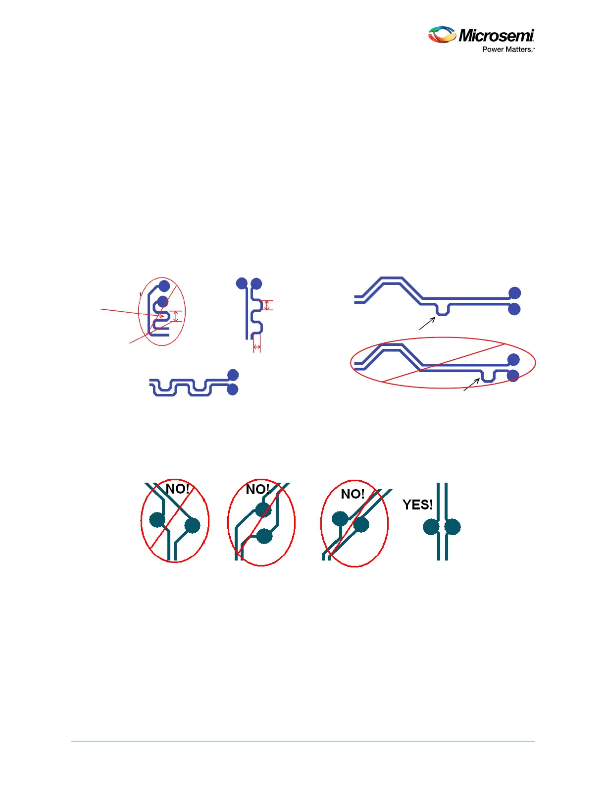
Figure 47 • Skew Matching
• The length of differential lanes should be matched within the TX and RX group.
This is applicable only to specific protocols like XAUI and so on.
• Route differential pairs symmetrically into and out of structures, as shown in the following figure.
Figure 48 • Example of Asymmetric and Symmetric Differential Pairs Structure
• Skin effect dominates as the speed increases. To reduce the skin effect, width of the trace has
to be increased (loosely coupled differential traces). Increase in trace width causes increase in
dielectric losses. To reduce the dielectric loss, use low Dissipation Factor (Df) PCB materials
like Nelco 4000-13. This is approximately double the cost of FR4 PCB material, but can provide
increased eye-opening performance when longer trace interconnections are required.
Remember to maintain 100
Ω differential impedance. Need to consider this if the data rate is 5
Gbps and above.
• Far end cross talk is eliminated by using stripline routing. However, routing in stripline causes
more dielectric loss and more variation in the impedance. Cross talk affects only when there is a
high density routing. It is better to route as microstrip, if there is enough space between
differential pairs (> 4 times the width of the conductor) to reduce dielectric loss. Simulations are
recommended to see the best possible routing.
Skew compensation
deviates too far away
from neighbor trace.
Trace-to-itself
spacing is too close.
Best way to
compensate for skew
Deviation must not
exceed 3X the nominal
trace-to-itself spacing
rule for the diff pair.
Trace-to-itself spacing
must be at least 4X the
trace width.
Skew is
compensated as
soon as it is needed.
Do not wait until the
end to put in skew
compensation
Multiple small
bumps are better
than one large
bump for skew
compensation
NO!