Creating Schematic Symbols Using Cadence OrCAD Capture CIS for SmartFusion2
and IGLOO2 Designs
AC393 Application Note Revision 14.0 76
4.2 Creating Schematic Symbols with User Defined Pin
Names
4.2.1 Exporting Pin Information from the Libero Design
1. Launch Libero and open project. For more information about how to use the System Builder wizard
in the Libero design, see
http://coredocs.s3.amazonaws.com/Actel/Tool/SysBuilder/sf2_system_builder_ug_1.pdf
http://coredocs.s3.amazonaws.com/Libero/Tool/SysBuilder/igl2_system_builder_ug_1.pdf
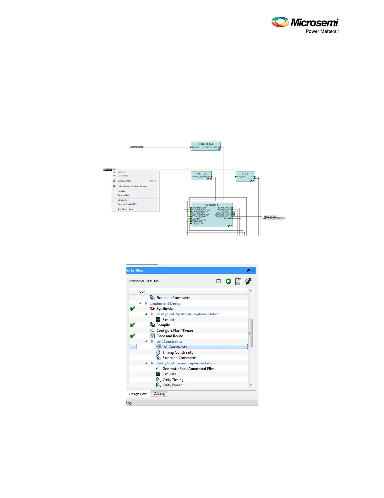
2. Right-click port to change the name and click Modify Port as shown in the following figure. Change
the name according to the requirement.
Figure 76 • Modifying Port Names
3. Check and verify all the pin names in the design. To verify the pin names, double-click I/O
Constraints in the Design Flow tab as shown in the following figure.
Figure 77 • I/O Constraints
 Loading...