Layout Guidelines for SmartFusion2- and IGLOO2-Based Board Design
AC393 Application Note Revision 14.0 67
The simulation tool generates the report where all the details are available. For example, Hyperlynx
generates the set of excel sheets which contain all setup and hold margin, overshoot, and undershoot
information for all corners. It also generates driver and receiver waveforms for all the nets.
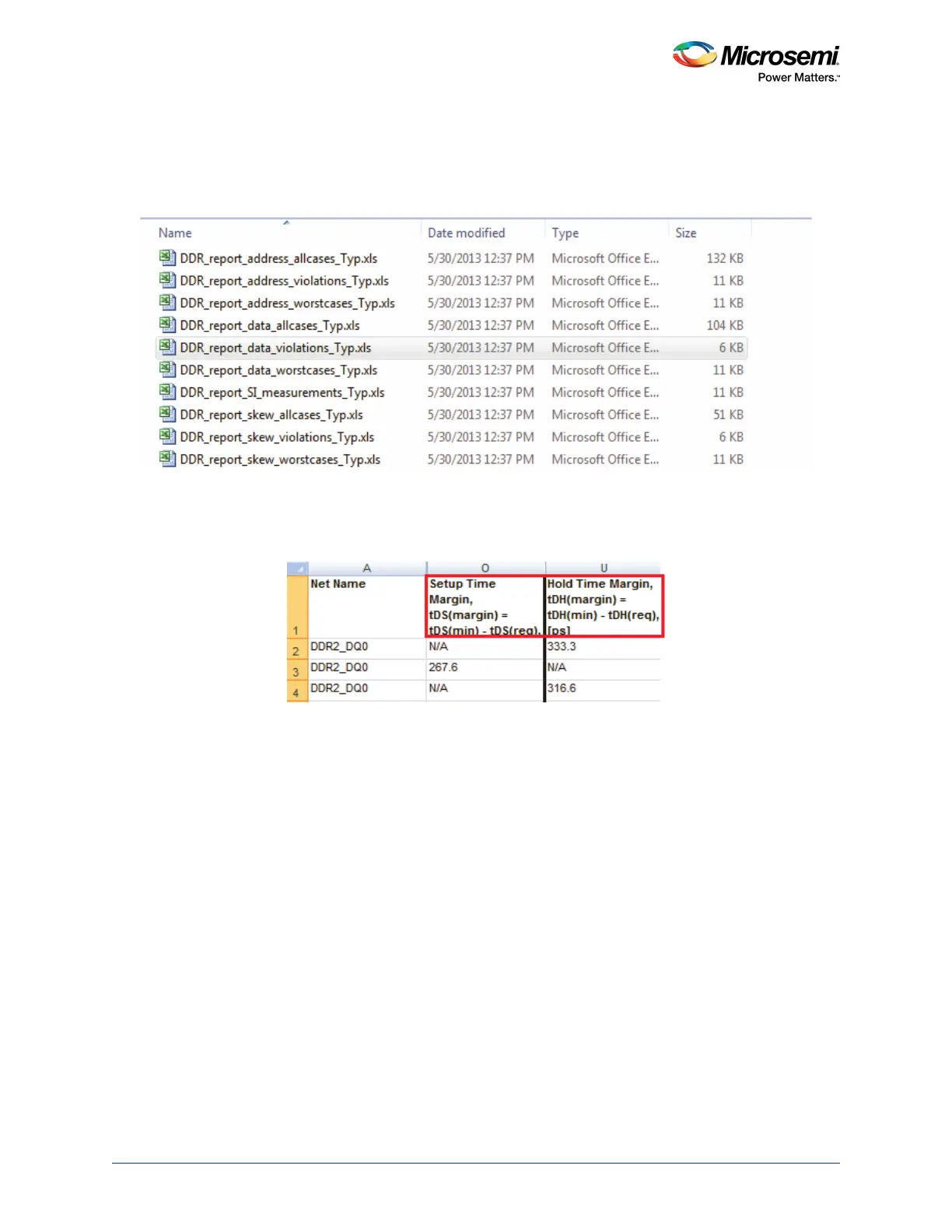
The following figure shows the file list where all the information regarding the simulation are stored.
Figure 64 • List of Reports Generated by Hyperlynx
The reports give setup and hold time for each net and also signal integrity details where overshoot and
undershoots are mentioned. The following figure shows the example of report for DQ0 net. It also shows
that the DQ0 has enough setup and holds time margins.
Figure 65 • Setup and Time Margins of DQ0
If any of the net is violating the setup and holding time margins, the length of the net should be changed
accordingly. If there is any high peak overshoot or undershoot, it might be because of the high value
termination resistor. It is required to adjust the value of ODT and re-iterate the simulation.
Figure 66, page 68 shows how to look at setup and hold time margins for DQ and DQS signals. Same is
applicable to the margin between the Command/Control/Address and CLK signals.
 Loading...