Board Design Guidelines for SmartFusion2 SoC and IGLOO2 FPGAs
AC393 Application Note Revision 14.0 27
2.8.1 PCI Express (PCIe)
PCIe is a point-to-point serial differential low-voltage interconnect supporting up to four channels. Each
lane consists of two pairs of differential signals: a transmit pair, TXP/TXN, and receive pair, RXP/RXN.
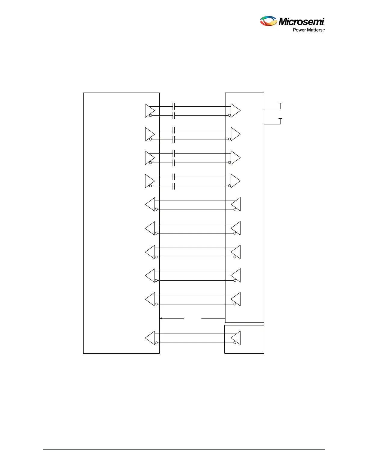
The following figure illustrates the connectivity between the SmartFusion2/IGLOO2 SerDes interface and
the PCIe edge connector.
Figure 15 • SerDes Schematics
2.8.2 AC Coupling
Each transmit channel of a PCIe lane must be AC coupled to allow link detection. Capacitors used for AC
coupling must be external to the device and large enough to avoid excessive low-frequency drops when
the data signal contains a long string of consecutive identical bits.
For non-PCIe applications, the SmartFusion2/IGLOO2 device requires the receive inputs to be AC
coupled to prevent common-mode mismatches between devices. Suitable values (for example, 0.1
µF)
for AC-coupling capacitors must be used to maximize link signal quality and must conform to DS0128:
IGLOO2 and SmartFusion2 Datasheet electrical specifications.
PCIe Edge
100 MHz
Differential
Clock
Source
+1 2 V
+3 . 3 V
Reset#
Fabric I/O
SerDes Lane0 / TXD
0.1 µF
0.1 µF
Tx Rx
SerDes Lane1 / TXD
0.1 µF
0.1 µF
Tx Rx
SerDes Lane2 / TXD
0.1 µF
0.1 µF
Tx Rx
SerDes Lane3 / TXD
0.1 µF
0.1 µF
Tx Rx
SerDes Lane0 / RXD
Rx Tx
SerDes Lane1 / RXD
Rx Tx
SerDes Lane2 / RXD
Rx Tx
SerDes Lane3 / RXD
Rx Tx
SerDes REFCLK0
Rx Tx
SerDes REFCLK1
Rx Tx
SmartFusion2/ IGLOO2
Connector
On-board