Appendix: Power Integrity Simulation Topology
AC393 Application Note Revision 14.0 94
9 Appendix: Power Integrity Simulation
Topology
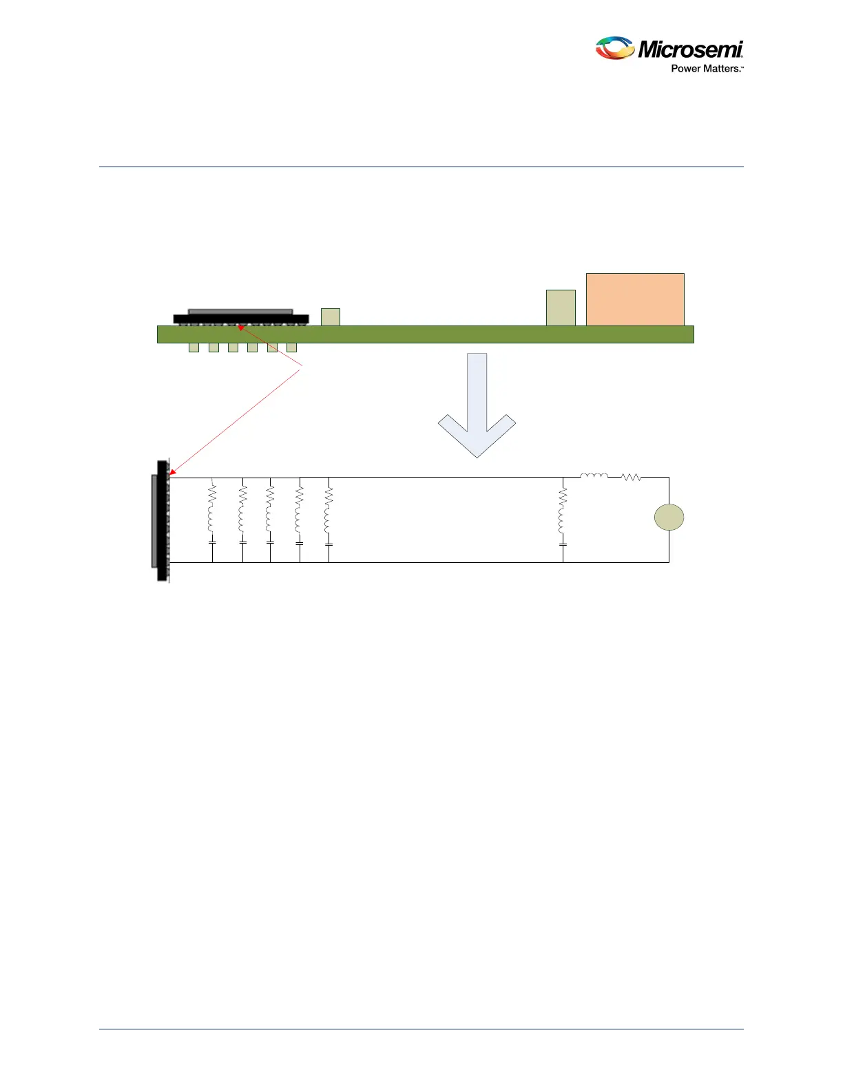
The following figure shows the topology that is considered for simulating the power plane for power
integrity analysis.
Figure 90 • Power Integrity Simulation Topology
PCB
Voltage
Regulator
Module (VRM)
Bulk
Caps
Bulk
Caps
De-coupling Caps
Impedance of the
plane is simulated at
this point
+
-
R
L
VRM
Bulk
Caps
Bulk
Caps
De-coupling Caps
Note: Package parameters of SmartFusion2 are not considered for simulations.