Board Design Guidelines for SmartFusion2 SoC and IGLOO2 FPGAs
AC393 Application Note Revision 14.0 37
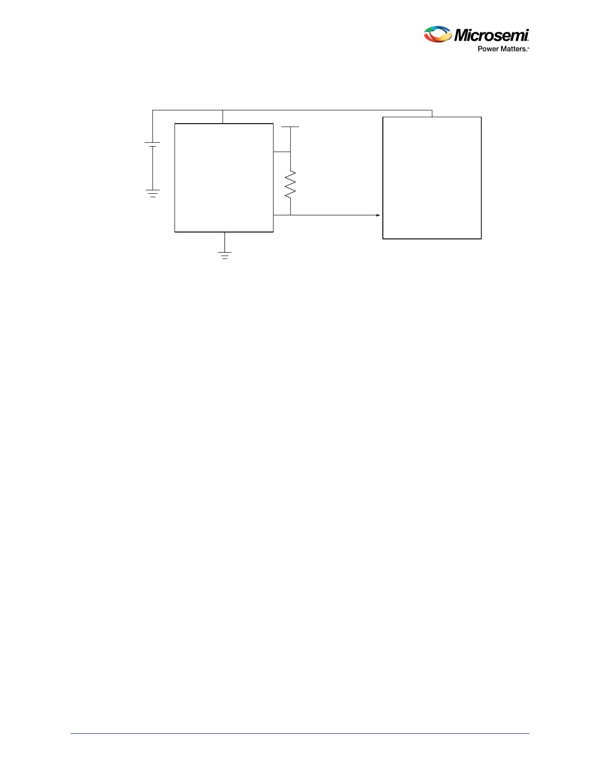
SmartFusion2/IGLOO2 devices do not have a built-in brownout detection circuitry, but an external
brownout detection circuitry can be implemented as shown in the following figure.
Figure 23 • BOD Circuit Implementation
The BOD device must have an open-drain output to connect to VPP through a 10 kΩ resistor externally.
During power-on, the brownout reset keeps the device powered down until the supply voltage reaches
the threshold value. Thereafter, the brownout reset device monitors VDD and keeps RESET# output
active as long as VDD remains below the threshold voltage. An internal timer delays the return of the
output to the inactive state (high) to ensure proper system reset.
The delay time is in milliseconds and starts after VDD has risen above the threshold voltage. When the
supply voltage drops below the threshold voltage, the output becomes active (low) again.
2.14 Simultaneous Switching Noise
When multiple output drivers switch simultaneously, they induce a voltage drop in the chip or package
power distribution. The simultaneous switching momentarily raises the ground voltage within the device
relative to the system ground. This apparent shift in the ground potential to a non-zero value is known as
simultaneous switching noise (SSN) or, more commonly, ground bounce.
For SSO guidelines for SmartFusion2 and IGLOO2 I/Os, see UG0445: SmartFusion2 SoC FPGA and
IGLOO2 FPGA Fabric User Guide.
Brownout Reset
Device
SmartFusion2/
IGLOO2
Sense
GND
+1.2 V
DEVRST_n
VDD
Reset#
10 kΩ
Supply
Supply