Creating Schematic Symbols Using Cadence OrCAD Capture CIS for SmartFusion2
and IGLOO2 Designs
AC393 Application Note Revision 14.0 72
Recommendations for arranging pins in the Section column:
• Arrange individual bank pins in separate sections
• Arrange all power supply pins in one section
• Arrange all ground pins in one section
• All passive pins can be in one section
• Arrange the remaining pins like Clock, JTAG, SERDES in one section.
4.1.2 Generating a OrCAD Capture Schematic Symbol
1. Invoke Cadence OrCAD Capture CIS.
2. Go to File > New > Library, then select the *.olb file.
3. Go to Design > New Part from Spreadsheet...
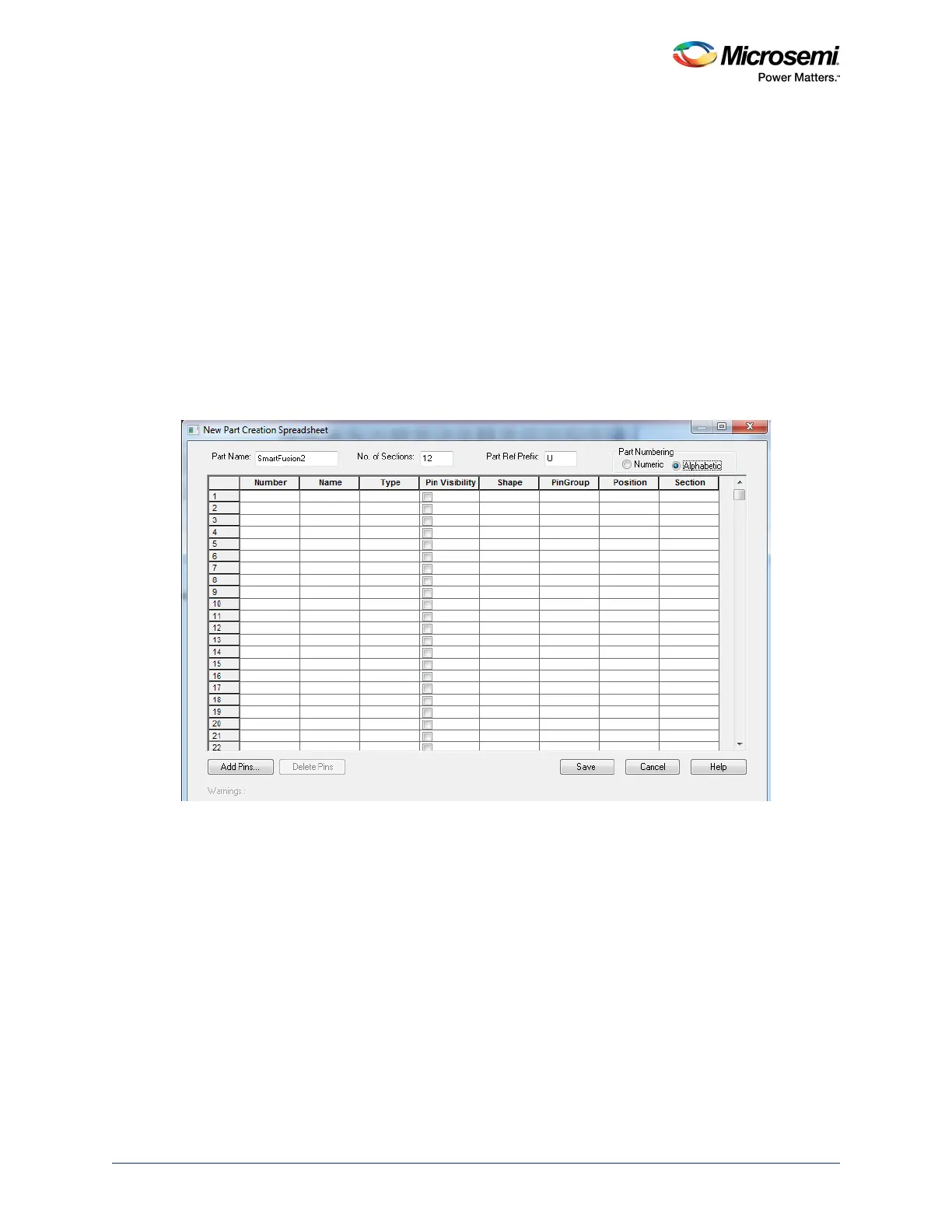
The New Part Creation Spreadsheet dialog appears as shown in the following figure.
4. In the New Part Creation Spreadsheet dialog, specify the following:
•Part Name
• Number of sections
• Part Ref Prefix - choose Alphabetic
Figure 70 • New Part Creation Spreadsheet Dialog