Board Design Guidelines for SmartFusion2 SoC and IGLOO2 FPGAs
AC393 Application Note Revision 14.0 13
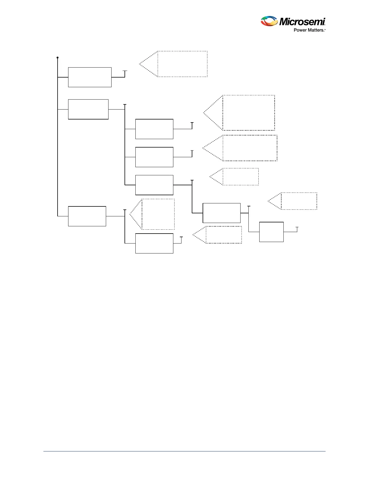
Figure 3 • Example Power Supply Topology
2.3.5 Unused Pin Configurations
In cases where certain interfaces are not used, the associated pins need to be configured properly. For
example, the pins of an unused crystal oscillator can be left floating (DNC) and must not be grounded. If
a PLL is not used or bypassed, and only the divider circuitry is used, then the PLL’s pins can be powered
without RC filter circuitry.
For SmartFusion2/IGLOO2 devices with multiple SerDes blocks, designers should tie off unused SerDes
blocks, as shown in Figure 4, page 14.
For banks configured as LPDDR or single-ended I/O (and MDDR or FDDR functionalities are not being
used), VREFx can be left floating (DNC) even though the corresponding bank supply is still powered.
To allow a SmartFusion2/IGLOO2 device to exit from reset, some of the bank supplies (VDDIx) must
always be powered, even if associated bank I/O are unused (as shown in Table 6, page 15 and Table 9,
page 17).
For details on bank locations for all the devices, see DS0115: SmartFusion2 Pin Descriptions Datasheet
or DS0124: IGLOO2 Pin Descriptions Datasheet.
+12 V
+5 V
+3.3 V
+2.5 V
+2.5 V
+1.8 V
DDR3_1P5
DDR3_VTT
+3.3 V
+1.2 V
VDDIO1_3P3
VDDIO7_1P8
VDDIO0_1P5
VDDIO3_3P3
VDDIO4_3P3
VDDIO8_3P3
VDDIO2_3P3
PTH08T230WAZ
Texas Instruments
NX7102
Microsemi
NX9415CMTR
Microsemi
MIC69502WR
Micrel
MIC69502WR
Micrel
MIC69502WR
Micrel
MIC37102YM
Micrel
MIC37102YM
Micrel
VDD
CCC_Sxy_PLL_VDDA
SERDES_x_VDD
SERDES_x_L01VDDAIO
SERDES_x_L23VDDAIO
VDDIO6_2P5
VDDIO9_2P5
SERDES_x_L01_VDDAPLL
SERDES_x_L23_VDDAPLL
TPS51200
Texas
Instruments
PLL_SERDES_x_VDDA
PLL_xDDR_VDDA
PLLMDDRVDDA
VPPNVM
VPP
VDDIO5_2P5