Layout Guidelines for SmartFusion2- and IGLOO2-Based Board Design
AC393 Application Note Revision 14.0 44
3.3.2.3 SerDes PLL
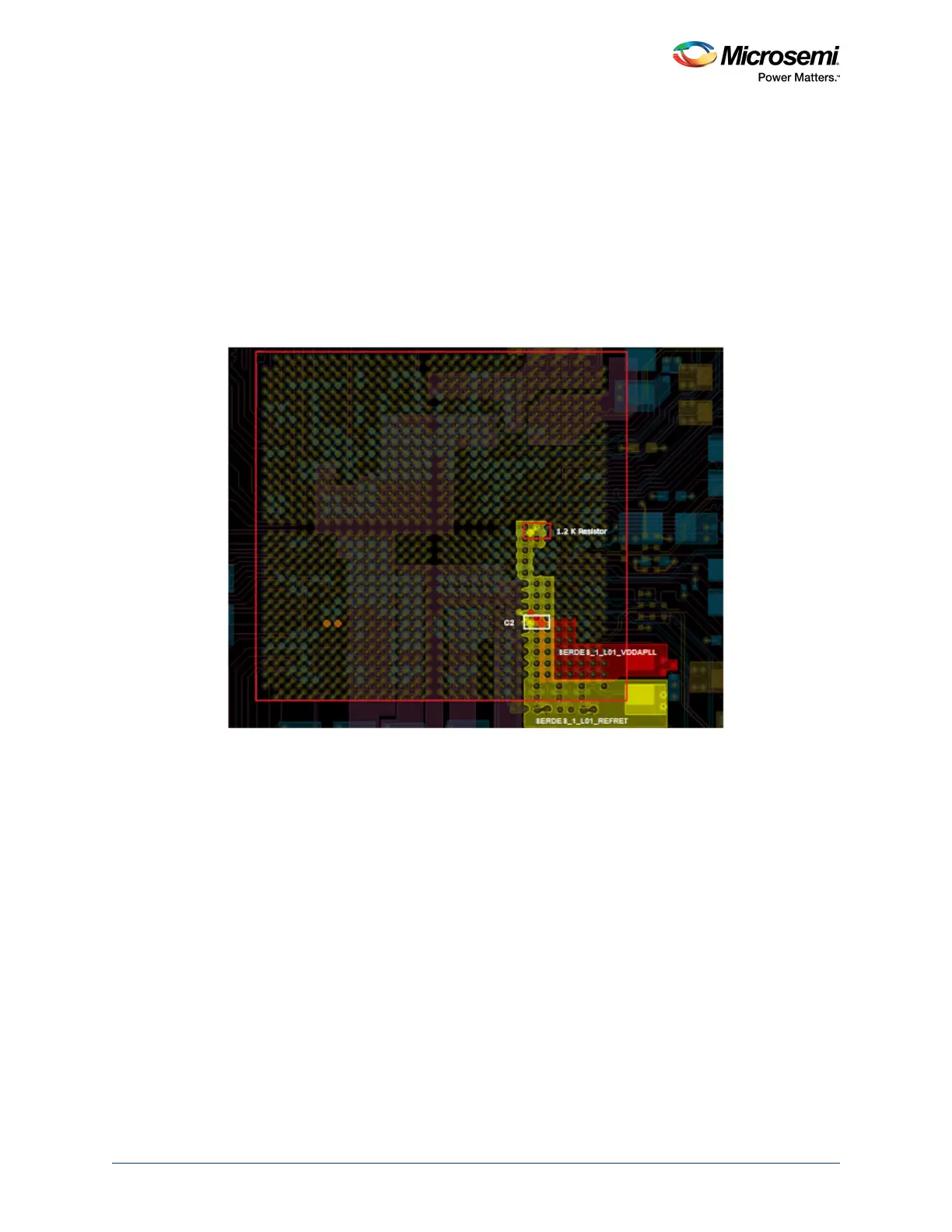
• Plane routing for SERDES_1_L01_VDDAPLL and SERDES_1_L01_REFRET is shown in the
following figure.
• SERDES_1_L01_VDDAPLL and SERDES_1_L01_REFRET should not be routed as traces. A
small trace width causes poor noise performance due to the high inductive behavior of the trace.
Even though the current requirement is low, these supply traces should be routed as small planes,
as shown in the following figure.
• The connections of 1.2 kΩ resistor and SERDES_1_L01_REXT of SmartFusion2/IGLOO2 should
not be routed as a thick plane. It must be routed as a signal trace in-order to meet minimum
capacitance requirement of the SERDES_1_L01_REXT pin. The length of the trace should be as
short as possible. The following figure shows the sample layout.
• Same layout guidelines should be followed for the remaining SerDes PLL power supplies.
Figure 32 • Layout of SERDES_1_L01_VDDAPLL and SERDES_1_L01_REFRET
3.3.3 Simulations
3.3.3.1 SerDes Core Power (SERDES_x_VDD)
The target impedance of the SERDES_x_VDD pin is calculated as 300 mΩ, based on the following
values (see Power Supply, page 38):
•V
SUPPLY
= 1.2 V
•I
trans
= 200 mA
• Ripple = 5%
Figure 33, page 45 shows the impedance of the plane (SERDES_x_VDD) improved by the decoupling
capacitors. The impedance of the plane is kept under 0.2 Ω till 100 MHz.