Creating Schematic Symbols Using Cadence OrCAD Capture CIS for SmartFusion2
and IGLOO2 Designs
AC393 Application Note Revision 14.0 74
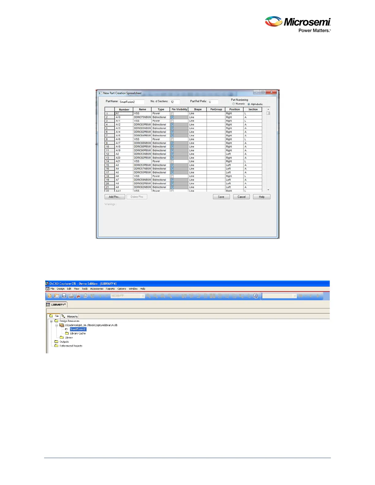
6. Select the top left cell of New Part Creation Spreadsheet dialog and paste the copied data. Check
if all the columns match between the Example PAT Spreadsheet and New part creation
Spreadsheet dialog as shown in the following figure.
Note: In the Pin Visibility column, select all the check boxes. Some of the check boxes for the power pins
might not be selected. If you want those pins to be visible, ensure that they are selected.
Figure 72 • New Part Creation Spreadsheet Dialog with Data
7. Click Save.
Note: When you click save, the Design Rule Check (DRC) operation is triggered. If there are any errors
reported during the DRC, modify the Example PAT Spreadsheet to fix those errors. If there are just
warnings and if you want to ignore them, click Continue to proceed with generating the Part.
Figure 73 • New Part created in the Library
 Loading...