Layout Guidelines for SmartFusion2- and IGLOO2-Based Board Design
AC393 Application Note Revision 14.0 43
3.3.2 Plane Layout
3.3.2.1 SerDes Core Power (SERDES_x_VDD)
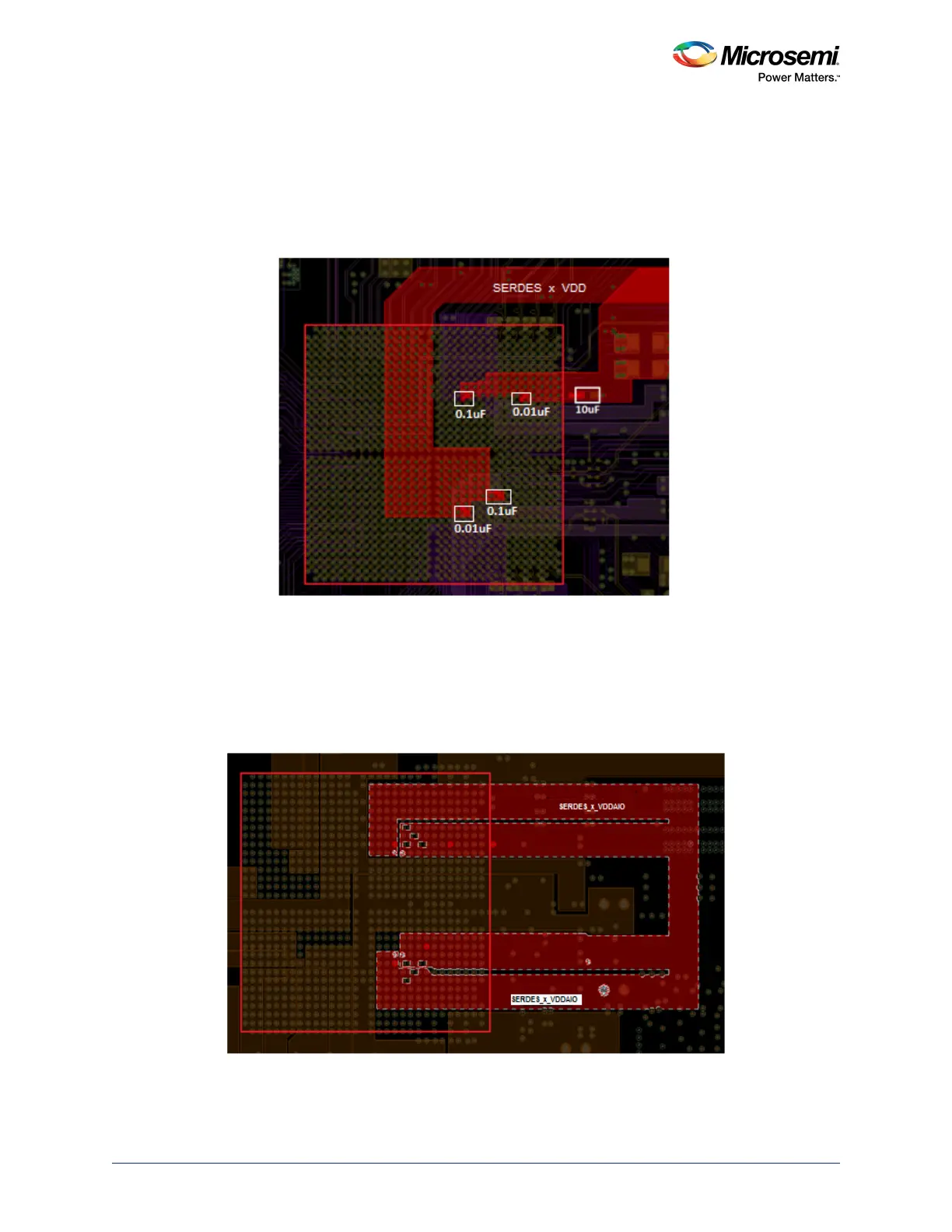
Even though SERDES0 and SERDES1 cores share the same power supply, separate planes must be
made while connecting to corresponding SerDes blocks, as shown in the following figure. This reduces
the noise coupling between SERDES0 and SERDES1 blocks.
Figure 30 • Layout for SERDES_x_VDD Plane
3.3.2.2 SerDes I/O Power (SERDES_x_VDDAIO)
• Even though SERDES0 and SERDES1 I/Os share the same power supply, make separate planes
while connecting to the corresponding pins, as shown in the following figure. Each plane is
separated as SERDES_0_L01_VDDAIO, SERDES_0_L23_VDDAIO, SERDES_1_L01_VDDAIO,
and SERDES_1_L01_VDDAIO, as shown in the following figure. This reduces the noise coupling
between the differential lanes.
Figure 31 • Layout of SERDES_x_VDDAIO Plane