Board Design Guidelines for SmartFusion2 SoC and IGLOO2 FPGAs
AC393 Application Note Revision 14.0 8
Decoupling capacitors other than those listed in the preceding table can be used if sized to meet or
exceed the performance of the network given in this example. However, substitution requires analysis of
the resulting power distribution system’s impedance versus frequency to ensure that no resonant
impedance spikes result. See Figure 1, page 5 for power supply schematics design.
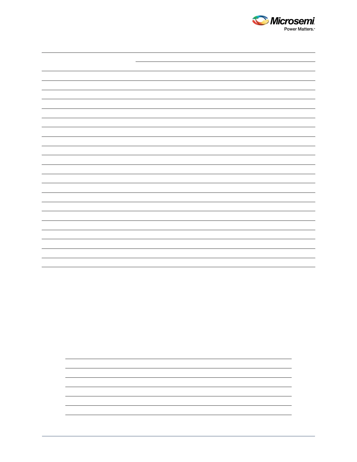
The following table lists the recommended decoupling capacitors for the SmartFusion2/IGLOO2 devices.
For placement and routing details, see Layout Guidelines for SmartFusion2- and IGLOO2-Based Board
Design, page 38.
VPPNVM 1 1 1
SERDES_0_VDD 2 1 1 1
2
SERDES_1_VDD 2 1 1 1
2
SERDES_0_L01_VDDAIO 1 1
2
1
2
1
3
SERDES_0_L23_VDDAIO 1 1
2
1
2
1
3
SERDES_1_L01_VDDAIO 1 1
2
1
2
1
3
SERDES_1_L23_VDDAIO 1 1
2
1
2
1
3
CCC_NE0_PLL_VDDA 1 1 1
CCC_NE1_PLL_VDDA 1 1 1
CCC_NW0_PLL_VDDA 1 1 1
CCC_NW1_PLL_VDDA 1 1 1
CCC_SW0_PLL_VDDA 1 1 1
CCC_SW1_PLL_VDDA 1 1 1
MSS_FDDR_PLL_VDDA 1 1 1
MSS_PLL_MDDR_VDDA 1 1 1
PLL_SERDES_0_VDDA 1 1 1
PLL_SERDES_1_VDDA 1 1 1
SERDES_0_L01_VDDAPLL 1 1 1
SERDES_0_L23_VDDAPLL 1 1 1
SERDES_1_L01_VDDAPLL 1 1 1
SERDES_1_L23_VDDAPLL 1 1 1
1. 220 µF is used to limit surge current for the VDD supply.
2. Single ceramic decoupling capacitor is required for both pins at the device.
3. Single ceramic decoupling capacitor is required for four pins at the device.
Table 3 • Recommended Capacitors
Part Number Manufacturer Description
GRM155R71C103KA01D Murata Ceramic 0.01 µF, 16 V, 10%, X7R, 0402
GRM155R71C104KA88D Murata Ceramic 0.1 µF, 16 V, 10%, X7R, 0402
GRM188R60J106ME47D Murata Ceramic 10 µF, 6.3 V, X5R, 0603
T491B475M016AT KEMET Tantalum 4.7 µF, 16 V, 20%, 1411
T491B226M016AT KEMET Tantalum 22 µF, 16 V, 20%, 1411
Table 2 • Power Supply Decoupling Capacitors (continued)
Pin Name
Number
of Pins
Ceramic Caps Tantalum Caps
0.01 µF 0.1 µF 10 µF 33 µF 22 µF 47 µF 100 µF 220 µF
1
330 µF
 Loading...