Chapter 5: Installation
Connecting Trunks to LSM-4 Module Ports
Inter-Tel
®
5000 Installation Manual – Issue 2.4, May 2008 Page 5-25
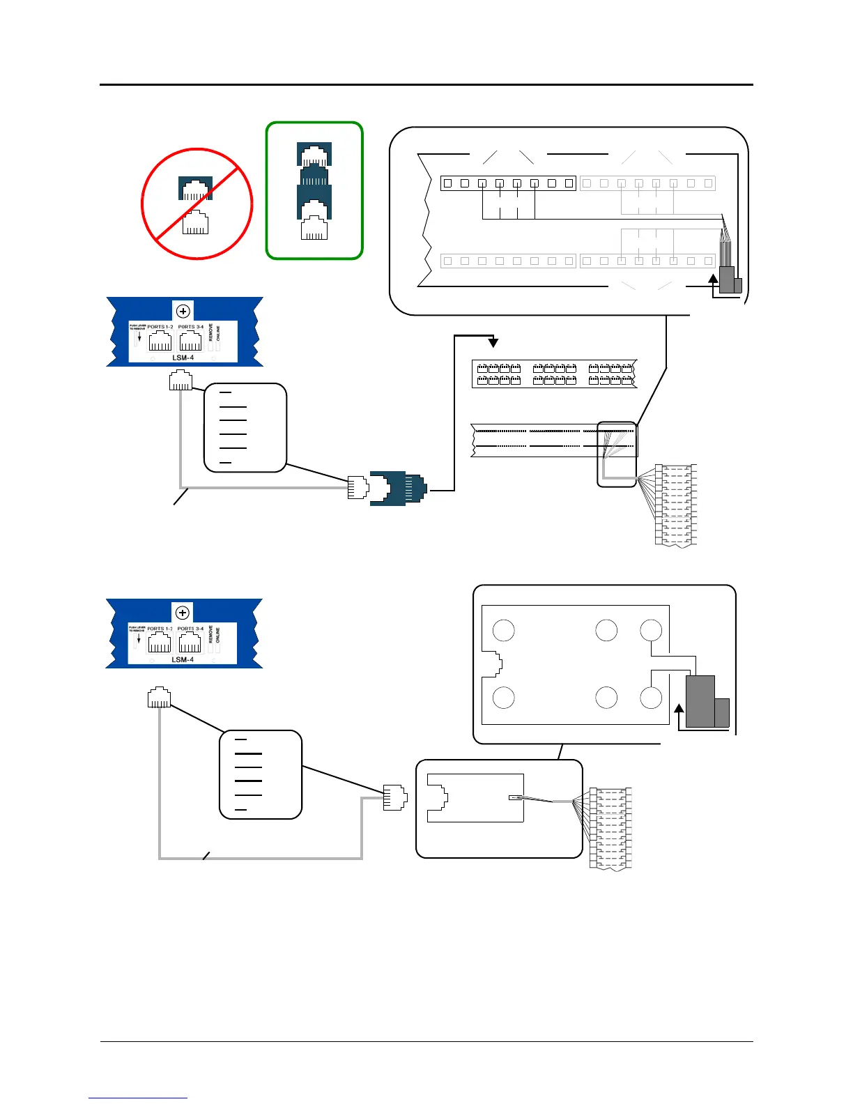
Figure 5-4. Cabling Option 1 – LSM-4
Figure 5-5. Cabling Option 2 – LSM-4
For additional lightning protection, install gas discharge tubes with silicon avalanche
suppressors to ground (grounding rod or copper cold water pipe) on each CO trunk. This must
be done external to the system. Each gas discharge tube is installed directly between the
service provider company RJ-type block and the system CO/DID/OPX input. This protection
should provide energy absorption and filter low-level surge potentials. Also, in areas with
frequent occurrences of lightning, make the cable length between the service provider company
RJ-type blocks and the gas discharge tubes at least 75 ft (22.5 m). The cable may be coiled as
needed.
1
2
3
4
5
6
not used
not used
T 1
R 1
T 2
R 2
8P/8C 110 Patch
8P/8C 110 Patch
66M1-50
Block
Adapter
6-pin plug
4- or 6-conductor
modular line cord
8P/8C 110 Patch Panel Back
1
2
T-1
2
35
6
7
8
9
10
11
12
13
14
15
16
17
18
R-1 T-2R-2
T-1 R-1 T-2R-2
1
2
3
468
57
3
4
LS 1
LS 2
SL 1
SL 2
8-pin Jack
6-pin Plug
RJ-14
to 8-pin jack
8-pin Jack
6-pin Plug
Adapter
NO YES
Back of Inter-Tel CS-5x00 Base Server
RJ-14
T-1 R-1 T-2R-2
LS 4
LS 3
Dual Single Line PortLSM-2 Module
Panel Front
Panel Back
1
4
25-Pair
cable from
MDF to
patch panel
Dual Loop Start Port
1
2
3
4
5
6
not used
not used
T 1
R 1
T 2
R 2
4- or 6-conductor
modular line cord
RJ-14
modular jack
assembly at rack
YEL
BLK
WHT
R2
RED
R1
T2
BLU
T1
GRN
66M1-50
Block
For each modular jack assembly
Back of Inter-Tel CS-5x00 Base Server
Top View
25-Pair cable
from MDF
to rack
RJ-14