Chapter 5: Installation
Single Line Module Pinouts
Inter-Tel
®
5000 Installation Manual – Issue 2.4, May 2008 Page 5-77
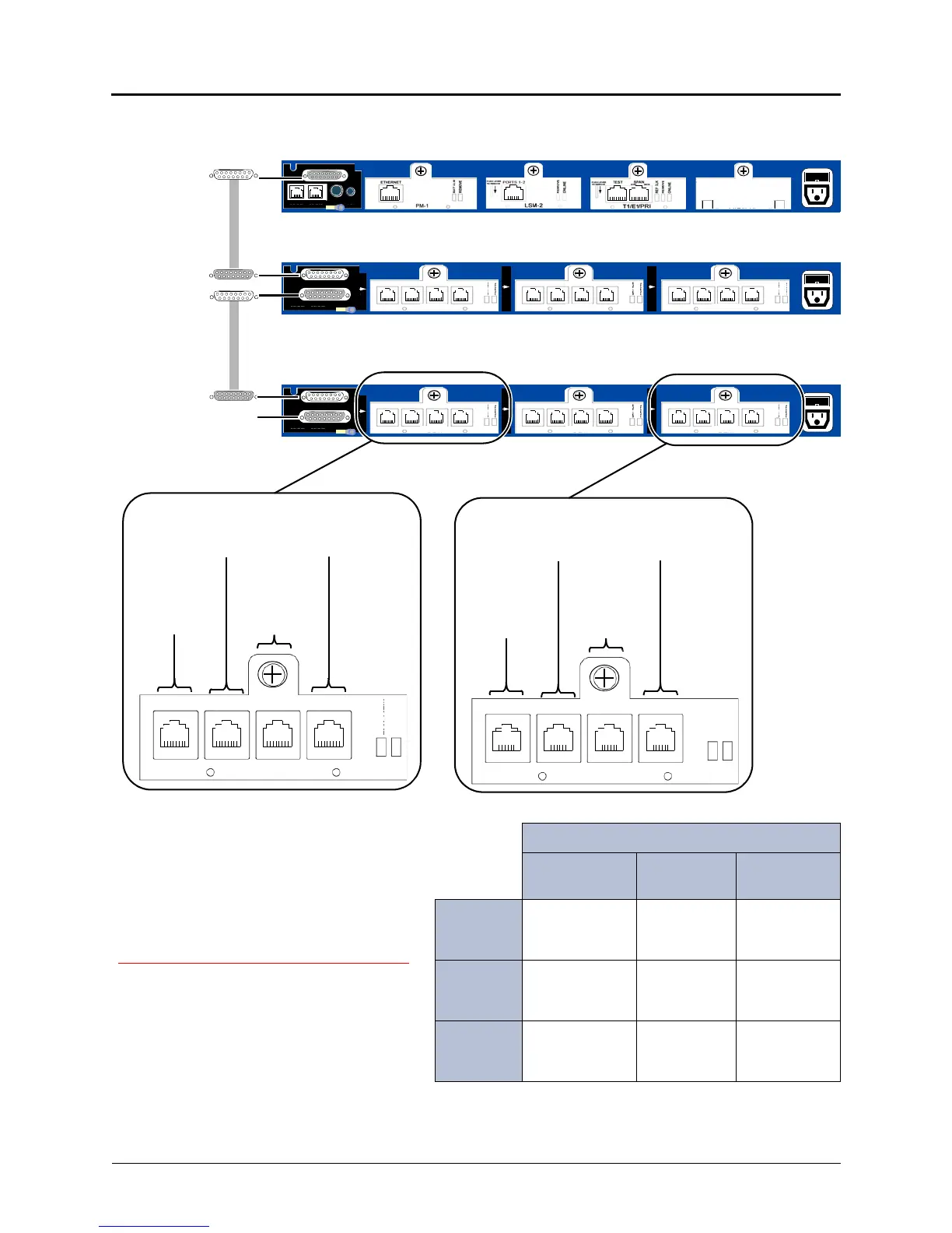
Figure 5-43. SLM-8 and DEM-16 Circuit Mapping Example
Circuits
Inter-Tel 5000
Base Chassis
DEI 1 DEI 2
Bay 1
1:01.1.X
through
1:01.2.X
1:04.1.X
through
1:04.16.X
1:12.1.X
through
1:12.16.X
Bay 2
1:02.1.X
through
1:02.30.X
1:05.1
through
1:05.8
1:13.1.X
through
1:13.16.X
Bay 3
Bay not
occupied
1:06.1.X
through
1:06.16.X
1:14.1 through
1:14.8
In this example, a T1/E1/PRI module is configured for E1/PRI.
Female to
Male to
Inter-Tel 5000
Male to DEI 1
Female to
Male to
external Voice Mail
DEM-16
1 – 4 5 – 8 9 – 12 13 – 16
BAY 1
EXP 2
EXP 1
DEM-16
1 – 4 5 – 8 9 – 12 13 – 16
EXP
DUAL LS
DUAL SL PA GE M OH
Inter-Tel 5000 Base Server
DEI 1
DEI 2
BAY 1/SYS 1
SLM-8
1 – 2 3 – 4 5 – 6 7 – 8
BAY 3
DEM-16
1 – 4 5 – 8 9 – 12 13 – 16
BAY 2
BAY 1
EXP 2
EXP 1
SLM-8
1 – 2 3 – 4 5 – 6 7 – 8
DEM-16
1 – 4 5 – 8 9 – 12 13 – 16
BAY 3
DEM-16
1 – 4 5 – 8 9 – 12 13 – 16
BAY 2
BAY 2/SYS 2 BAY 3/SYS 3
BAY 1/SYS 4 BAY 2/SYS 5 BAY 3/SYS 6
BAY 1/SYS 12 BAY 2/SYS 13 BAY 3/SYS 14
Circuits
1:12.1.X
to
1:12.4.X
Circuits
1:12.5.X
to
1:12.8.X
Circuits
1:12.9.X
to
1:12.12.X
Circuits
1:12.13.X
to
1:12.16.X
813.1806
BUSY
ONLINE
BUSY
ONLINE
BUSY
ONLI NE
BUSY
ONLINE
BUSY
ONLINE
BUSY
ONLINE
BUSY
ONLINE
Base Server
chassis
(DEI Cable
part no. 813.1847
or 813.1847-001)
SLM-8
1 – 2 3 – 4 5 – 6 7 – 8
Circuits
1:14.1
and
1:14.2
Circuits
1:14.3
to
1:14.4
Circuits
1:14.5
to
1:14.6
Circuits
1:14.7
to
1:14.8
BUSY
ONLINE
cable part no.
DEI 1
DEI 2
LEGEND:
BAY 1/SYS 4
=
Bay # in the chassis is the same
as the equivalent System # in
Message Print.
 Loading...


