60M1-50-Type
Block
(Part of MDF)
MODULAR
JACK
ASSEMBLIES
1.1.1
1.2.1
1.1.1
1.2.1
W/BL
BL/W
W/O
O/W
Y/BL
BL/Y
TIP
RING
TIP
RING
RING
TIP
G
R
Y
BK
G
R
Y
BK
1.16.1
1.16.1
TIP
RING
RING
TIP
To Digital
Endpoint or
Single-Line
Adapter
To Digital
Endpoint or
Single-Line
Adapter
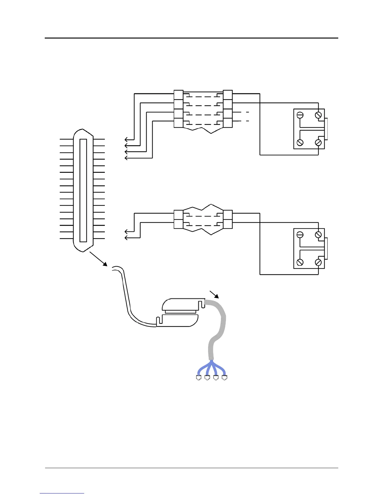
To DEI and DEM-16s
Amphenol-Type
Connector
to DEM-16
adapter cable*
*Available Adapter Cable:
15 ft (4.5720 m) with Amphenol (part no. 813.1814)
Amphenol
For simplicity, this figure shows digital
phones being installed using one-pair cable
and four-conductor modular jacks. If two-pair
cable or three-pair cable is used instead,
extra terminal blocks and the use of cross-
connect wiring techniques are required.
Note that tip and ring are connected to the
second pair of terminals (black and yellow)
on the modular jack.
 Loading...


