Chapter 5: Installation
Eclipse IP PhonePlus
Inter-Tel
®
5000 Installation Manual – Issue 2.4, May 2008 Page 5-109
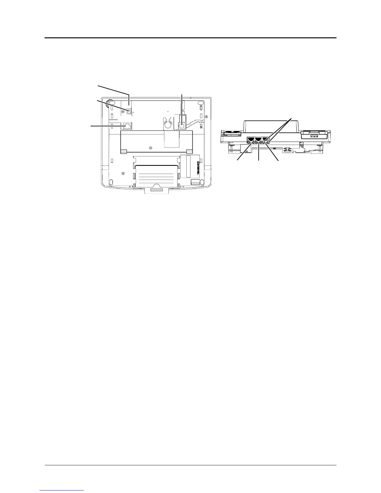
Eclipse IP PhonePlus
The Eclipse IP PhonePlus operates on either 10Base-T or 100Base-T LANs, while the Inter-Tel
5000 platform operates only on 100Base-T LANs. The following illustration depicts the
connection interfaces on the bottom and back of the endpoint.
The Eclipse IP PhonePlus provides the following connection interfaces:
• LAN/POWER Jack: Connects to an external power supply or a network hub/switch.
• Barrel Jack: Connects to an external power supply.
• Ports 1, 2, and 3 (OUT TO PC Jack): Connects up to three other IP devices, such as
PCs, notebooks, and printers.
• LEDs: Two LEDs indicate activity on each port:
o Link Status: When the link is valid, the green LED on the left side of the port lights.
When receive or transmit activity occurs on the link, the LED flashes.
o Collision: When both receive and transmit activities occur on the link at the same time,
the yellow LED on the right side of the port lights.
• Handset Jack: Connects to a handset.
For information about programming an Eclipse IP PhonePlus, refer to the Programming chapter
in the Inter-Tel 5000 Features and Programming Guide (part no: 580.8006).
DC
Barrel Jack
HANDSET Jack
The center
PORT 3
LAN/
PORT 1 PORT 2
Bottom
LEDs
Back
POWER
is positive.