Chapter 5: Installation
Model 8600 Series Endpoints
Inter-Tel
®
5000 Installation Manual – Issue 2.4, May 2008 Page 5-113
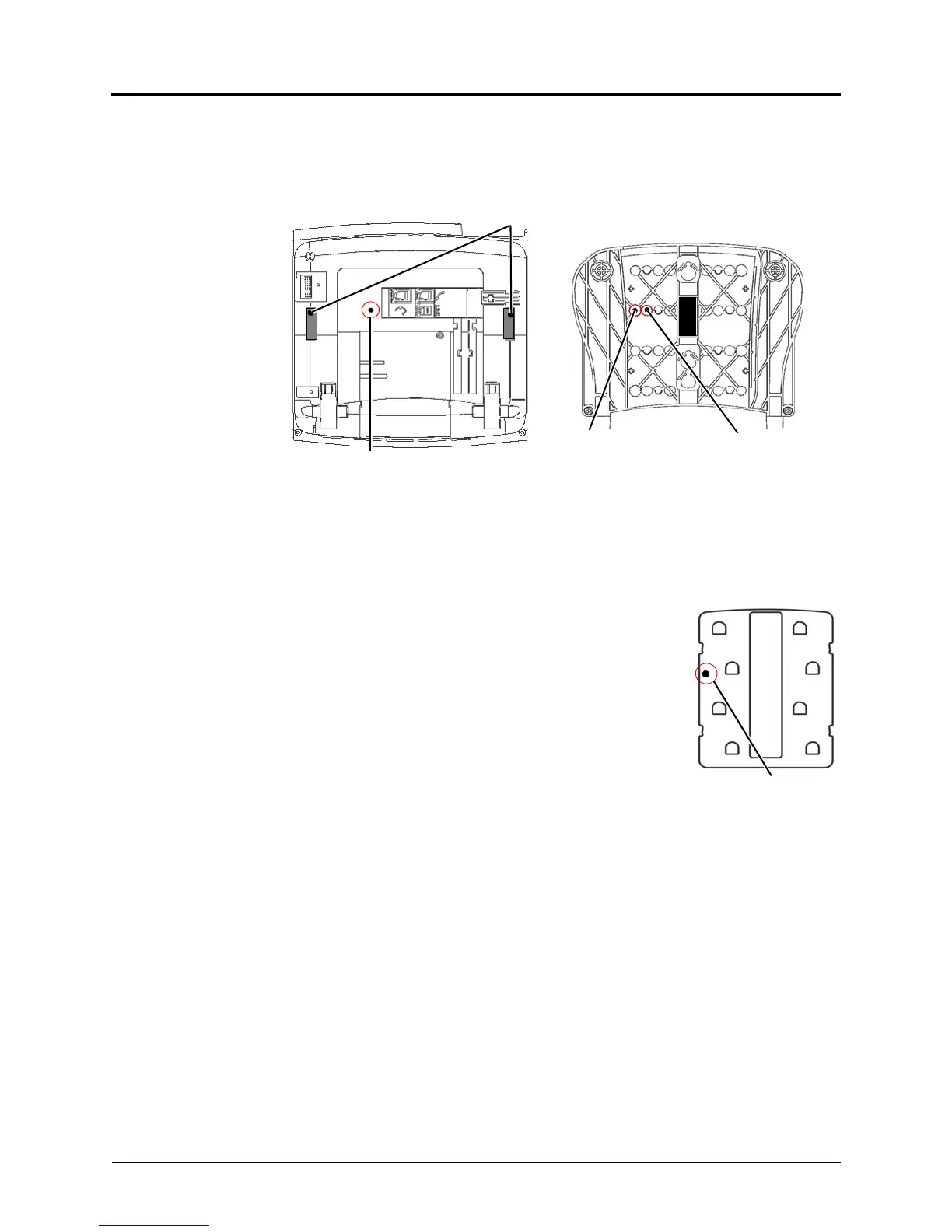
To wall-mount Model 8600 series endpoints with release buttons on the bottom housing:
1. Close the base completely so that it lies flat against the endpoint. (Rivet hole 1 on the
base aligns with the rivet hole on the bottom housing of the endpoint.)
2. Plug the four-inch line cord into the jack on the back of the endpoint and thread the line
cord through the wall-mount knockout on the base.
3. Insert one of the plastic rivets in rivet hole 1 on the base (see the illustration above) and
press it into the rivet hole on the endpoint. This locks the base to the endpoint.
4. Test the base to verify that it is securely locked to the
endpoint.
5. Reattach the metal plate to the endpoint base.
6. Insert the remaining plastic rivet through rivet hole 3 (as
shown at right) in the metal plate and press it firmly into rivet
hole 2 in the base. This locks the metal plate to the base.
7. Plug the line cord into the jack on the wall-mount bracket
and position the endpoint securely on the wall-mount
bracket.
8. Flip the handset hanger down to the horizontal position and
lock it into place. This holds the handset in place.
Rivet Hole
Base
Rivet Hole 1
Release Buttons
Bottom Housing
Rivet Hole 2
(Base not shown)
(Used to lock base(Used to lock metal
plate to base) to bottom housing)
 Loading...


