Chapter 5: Installation
Review and Update for Enabling a Voice Processor
Page 5-174 Inter-Tel
®
5000 Installation Manual – Issue 2.4, May 2008
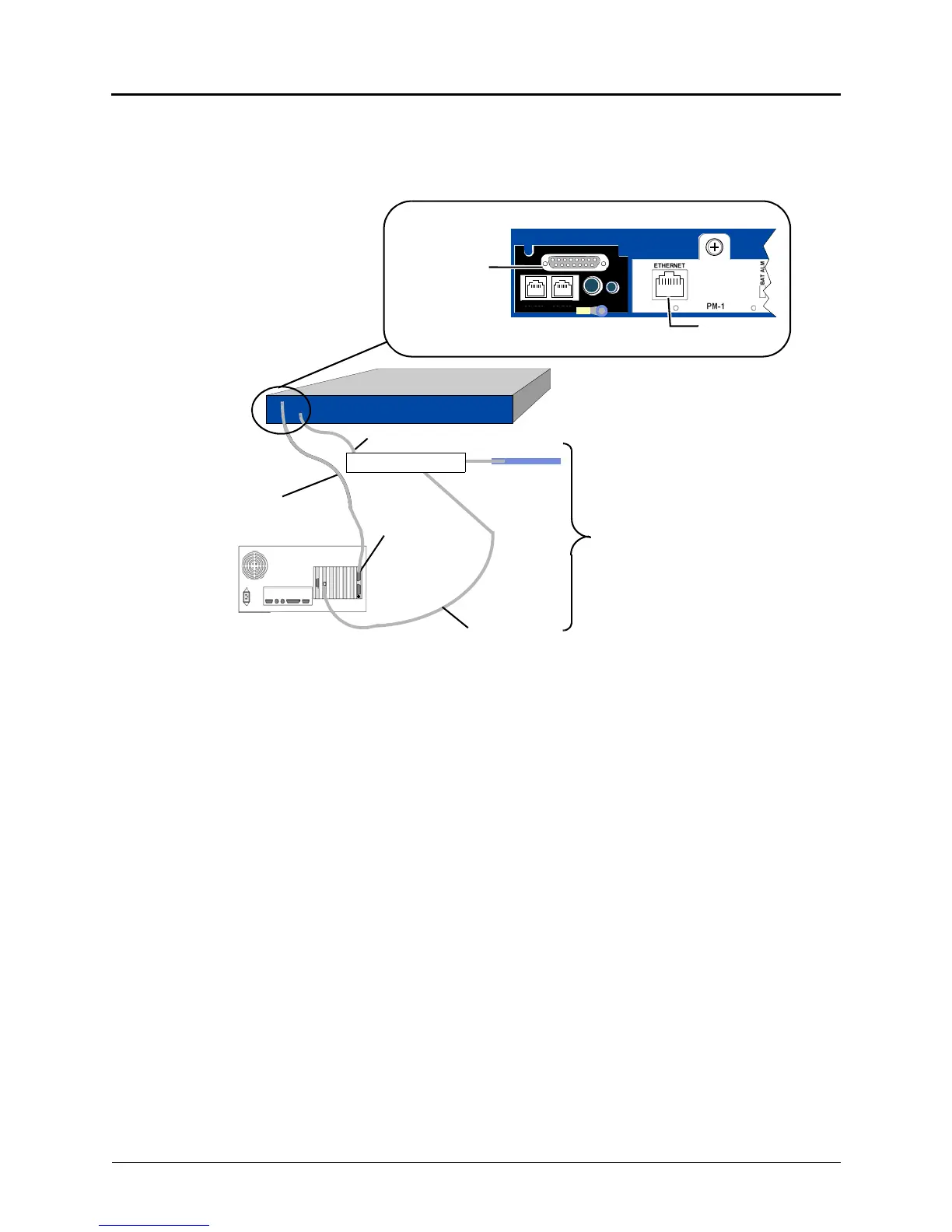
Figure 5-65 shows how a VPU connects to the Inter-Tel CS-5200/5400/5600 Base Server. An
8.5 ft (2.5 m) cable is available (part no. 813.1806). Or, if necessary, contact the Inter-Tel
CommSource division for information on purchasing longer cable lengths.
Figure 5-65. Example External Voice Mail Connection to Inter-Tel CS-5x00
Connection
Back of Inter-Tel 5000 Base Server
Optional
DB-15
adapter to
Cable to external VM
DB-15 PCM
(part no. 813.1806)
LAN
Ethernet
to LAN via
Ethernet to LAN via switch
Inter-Tel 5000 Base Server
to VM only
switch
Ethernet
to LAN via switch
SWITCH*
(see Figure
4-22)
Components
* Use a switch instead
of a hub. Hubs blindly
transmit traffic from all
ports to all other ports
increasing the
likelihood of LAN
congestion (for
example, Ethernet
collisions). Switches
intelligently segregate
the traffic so that each
port does not need to
compete with other
ports for LAN
bandwidth.
Optional External-VM
(not using DEI)
DUAL LS
DUAL SL
EXP
PAGE MO H