MPI – Troubleshooting
13-27
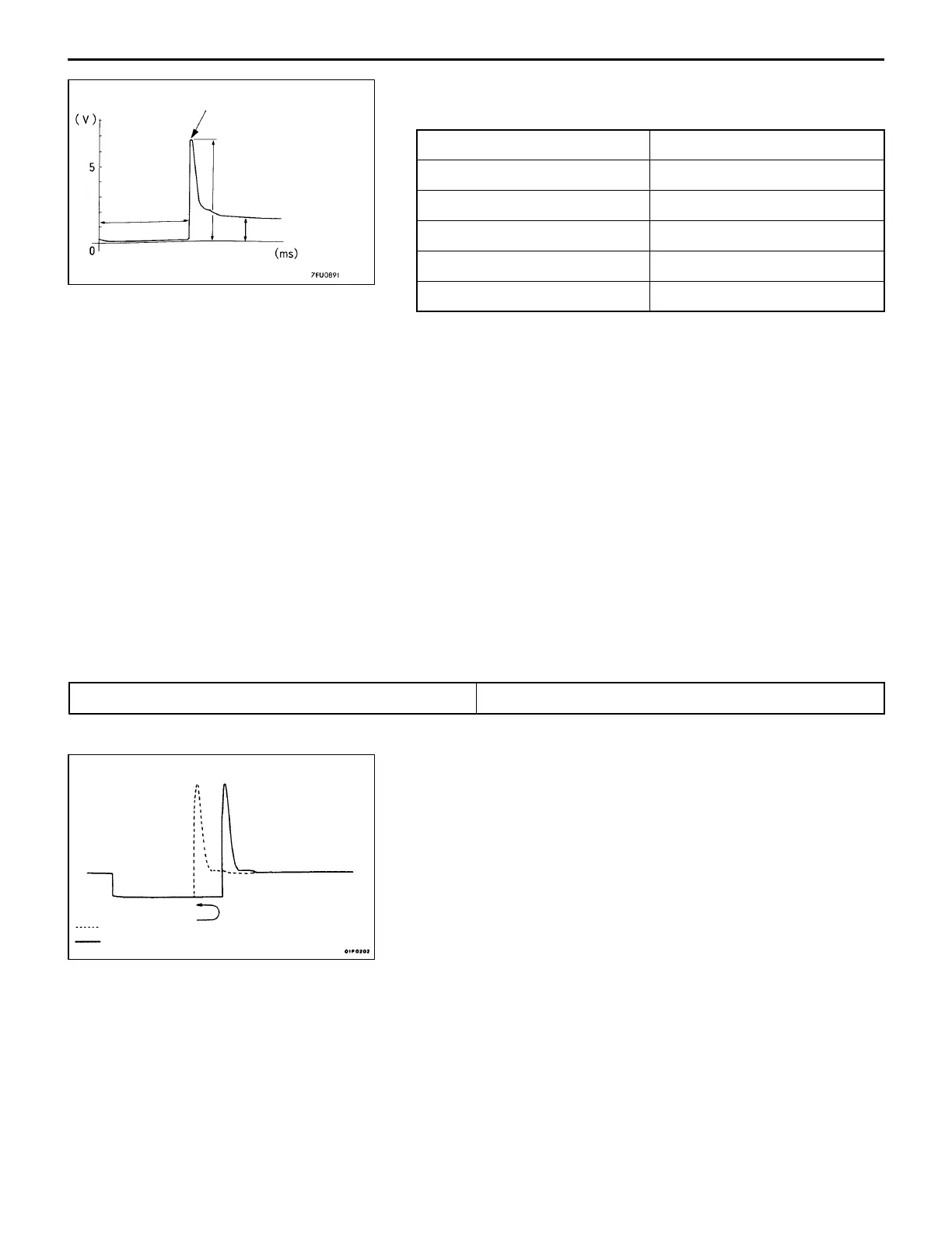
<Standard waveform>
Observation conditions
Probe selector switch × 10
AC-GND-DC DC
VOLTS/DIV. 1 V
TIME/DIV. 0.5 ms
Misc. –
Engine speed Idle
<Explanation on waveform>
The power supply voltage is being normally applied and, when a signal is received from the engine
ECU, the voltage drops to around 0 V for the period of time equivalent to its drive signal.
When the signal from the engine ECU turns OFF, the counter emf of the coil causes a voltage peak
to develop, thus resuming the power supply voltage.
Injector drive time:
The fuel injection time as determined by the engine ECU according to the output values of sensors
including AFS. Injector drive time = effective injection time + invalid injection time (Invalid injection
time: corrects operation time lag caused by a power supply voltage drop)
Solenoid coil counter emf:
When the signal from the engine ECU turns OFF, counter emf occurs in the injector coil (approx.
65 to 75 V).
Power supply voltage:
The power supply voltage is being applied in the absence of a signal from the engine ECU. If this
voltage is low, it extends the invalid injection time and, thus, the drive time.
<Waveform observation points>
Point A: Strength of solenoid coil counter emf
Solenoid coil counter emf is low or zero. Injector solenoid shorting
Point B: Injector drive time
When the engine is suddenly raced, the drive time temporarily
extends by a wide margin and soon returns to the normal
drive time corresponding to the engine speed.
Point A
Point B
Injector
drive time
Solenoid counter emf
(approx. 7 × 10 V)
Power supply voltage
At idle
During racing
 Loading...