MPI – Troubleshooting
13-28
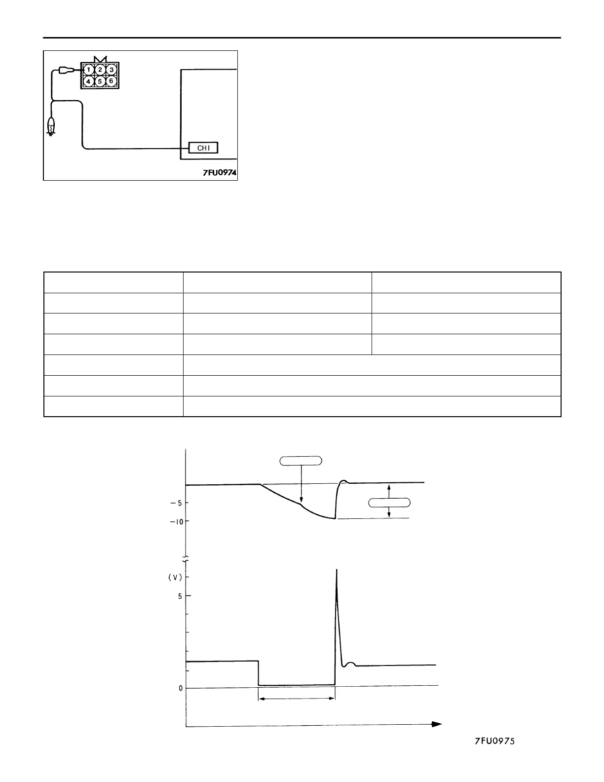
Injector Power Supply Voltage (Oscilloscope 2)
<Measurement procedure>
(1) Disconnect the resistor connector and connect the special
tool (Harness Connector: MD998463) to the circuit.
(2) Connect the oscilloscope probe to resistor connector
terminal (1) (special tool red clip) when the waveform
is observed with no. 1 cylinder, to terminal (4) (black
clip) when the waveform is observed with no. 2 cylinder,
to terminal (5) (green clip) when the waveform is observed
with no. 3 cylinder, and to terminal (6) (yellow clip) when
the waveform is observed with no. 4 cylinder.
(3) For the power supply voltage, observe the waveform of
the injector control signal at the same time. (Refer to
P.13-26 for the injector control signal measurement
procedure.)
<Standard waveform>
Observation conditions
Injector power supply voltage waveform Injector control signal
Probe selector switch × 1 × 10
AC-GND-DC AC DC
VOLTS/DIV. 5 V 1 V
TIME/DIV. 0.5 ms
Misc. To be timed with injector control signal
Engine speed Idle (850 rpm)
Injector power supply
voltage waveform
(oscilloscope 2)
Injector control signal
waveform
(oscilloscope 1)
Plunger in fully
opened position
Point B
Point A
Fuel injection time
Time
 Loading...