129
Rev. 2.0
07/27/2023
MBDV Hardware Manual
Parameter Instruction Name Defaults Range Unit
Related
Patterns
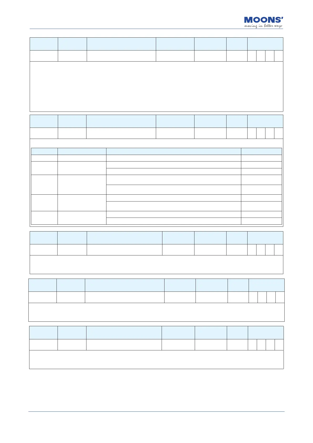
P0-24 UC 1st command torque lter frequency 1099 0 ~ 40000 01Hz P S T
Filter the command torque.
The lter is a single-output low-pass lter, which is used to low-pass lter the output of the PID controller (that is, the reference
current). System operation needs to be considered when setting this value.
The smaller the value, the lower the ltering frequency and the more obvious the ltering eect. The default value of 1099 works for
most applications. This value can be modied in cases of motor vibrations or abnormal audible noise.
An example use case is when a system is prone to mechanical resonance. The low pass lter cuto frequency can be set below the
resonance frequency of the system to prevent the motor control loop from exciting the system into its resonance frequency. In large
inertia applications, increasing KP can help improve the system response but a KP value set too high can induce vibrations. To reduce
those vibrations, this lter's frequency may be reduced.
Parameter Instruction Name Defaults Range Unit
Related
Patterns
P0-33 SD Automatic gain switching method 0 0 ~ 4
——
P S T
Set the parameter tuning method.
Set value Switching mode Switching condition Switching latency
0 Fixed in Group One Fixed in Group One -
1
According to positional
error
Switch to Group 2: Absolute position error ≥ P0-34 setting
P0-37
Switch back to Group 1: Absolute position error < P0-34 setting
P0-38
2
According to the actual
speed of the motor
Switch to group 2 conditions: absolute value of actual speed 35 P0-35
set value
P0-37
Switch back to Group 1: Absolute value of actual speed < P0-35 set
value
P0-38
3
According to the actual
output torque of the
motor
Switch to Group 2: Absolute value of actual torque P P0-36 set value
P0-37
Switch back to Group 1: Absolute value of actual torque < P0-36 set
value
P0-38
4
Position arrival signal
Switch to Group 2 condition: Position arrival condition is valid.
P0-37
Switch back to Group 1 condition: Position arrival condition not valid
P0-38
Parameter Instruction Name Defaults Range Unit
Related
Patterns
P0-34 PN Gain switching condition - position error 0 0 ~ 2147483647 Pulses P S T
Set the judgment condition for position error-based gain switching.
When in position control, P0-33 Gain parameter switching method is set to " 1 ", this parameter is used to set the judgment condition
for switching.
Parameter Instruction Name Defaults Range Unit
Related
Patterns
P0-35 VN Gain switching condition - actual velocity 0.000 0 ~ 100 rps P S T
Set the gain switching judgment condition based on the actual motor speed.
When in position control, velocity or torque control, P0-33 gain parameter switching method is set to " 2 ", this parameter is used to set
the judgment condition for switching.
Parameter Instruction Name Defaults Range Unit
Related
Patterns
P0-36 TN Gain switching condition - actual torque 10 0 ~ 3000 0.1% P S T
Set the gain switching judgment condition based on the actual output torque of the motor.
When in position control, velocity or torque control, P0-33 gain parameter switching method is set to " 3 ", this parameter is
used to set the judgment condition for switching.