Chapter 4 mV(ORP) MEASUREMENT
4.2 Functions in mV Measurement
58 HORIBA
4.2 Functions in mV Measurement
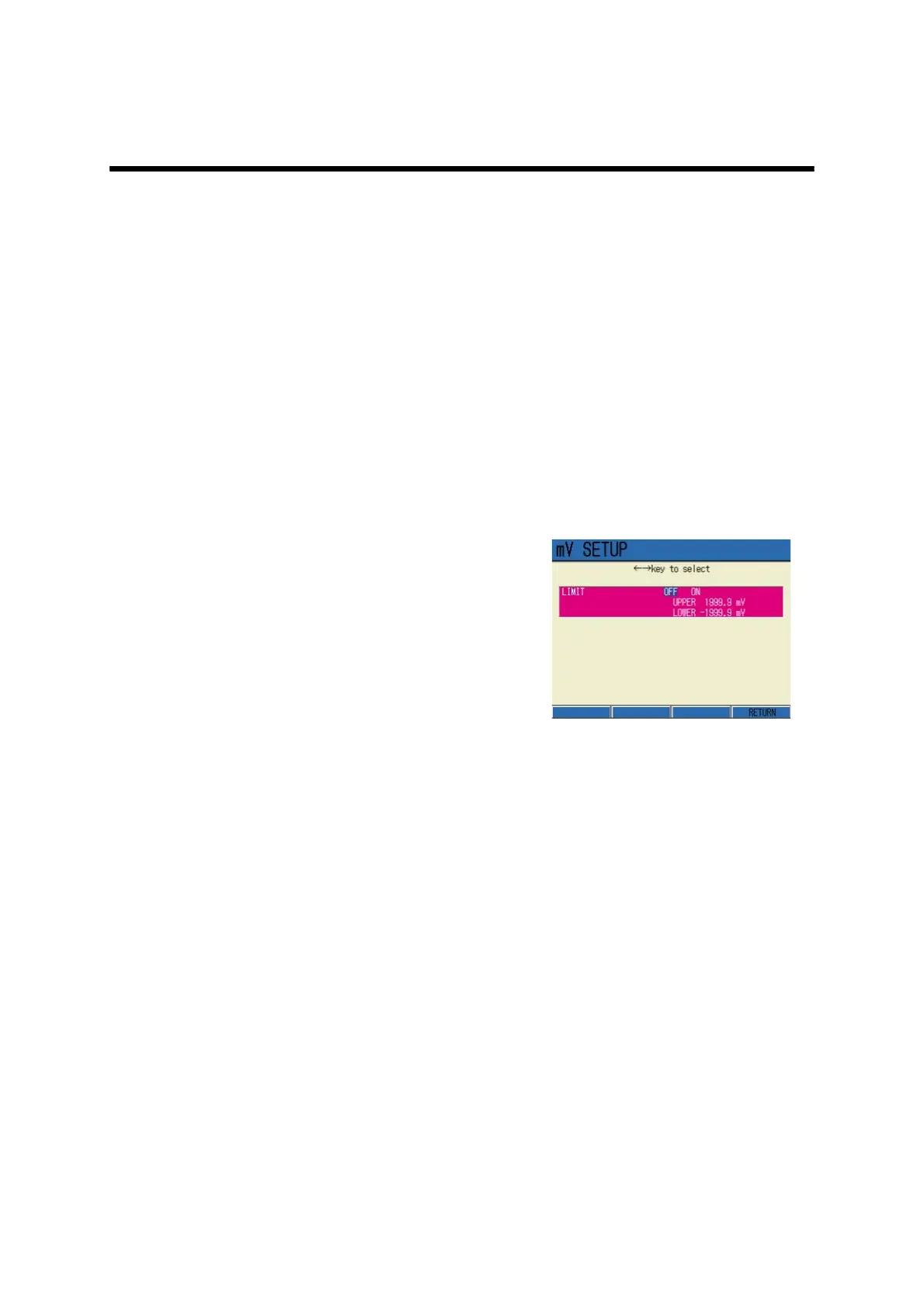
● Alarm setting
Alarm setting function detects if the measured values are over or below the upper/lower lim-
its, and displays them on the screen or outputs them as signals from the external output termi-
nals.
When the measured values are out of the alarm range, the display color of the screen changes:
Setting range: -1999.9 to +1999.9 mV (for both upper and lower limits of the alarm)
Setting procedure
1. In the mV Measurement screen,
press F1 (mV SETUP) to go to mV
SETUP screen.
2. Press ← or → key, and select
LIMIT ON.
3. Press the ENTER key.
The screen moves to the upper limit
value setting field.
4. Press the ENTER key again.
The display color of the setting field
changes, and the values can be input.
First, the upper limit values should be
under selection.
5. Press ↑ or ↓ key to input the val-
ues, and determine the setting by
the ENTER key.
The display color changes.
6. Press ↓ key to select the lower
limit option.
7. Press the ENTER key.
The display color of the setting field
changes, and the values can be input.
8. Press ↑ or ↓ key to input the val-
ues, and determine the setting by
the ENTER key.
The display color changes.
9. Reflect the setting by F4
(RETURN). The screen returns to
the Measurement.