Chapter 8 RESISTIVITY MEASUREMENT(F-54, 55)
8.2 Setting Configuration
110 HORIBA
8.2 Setting Configuration
● Setting resistivity alarm
Resistivity alarm detects if the measured val-
ues are out of upper or lower limit values,
and displays them on the screen or outputs
them as signals from the external output ter
-
minals.
When the values are out of the set alarm
range, the display color on the screen
changes.
1. In the RESIST Measurement
screen, press F1 (RESI. SETUP)
key.
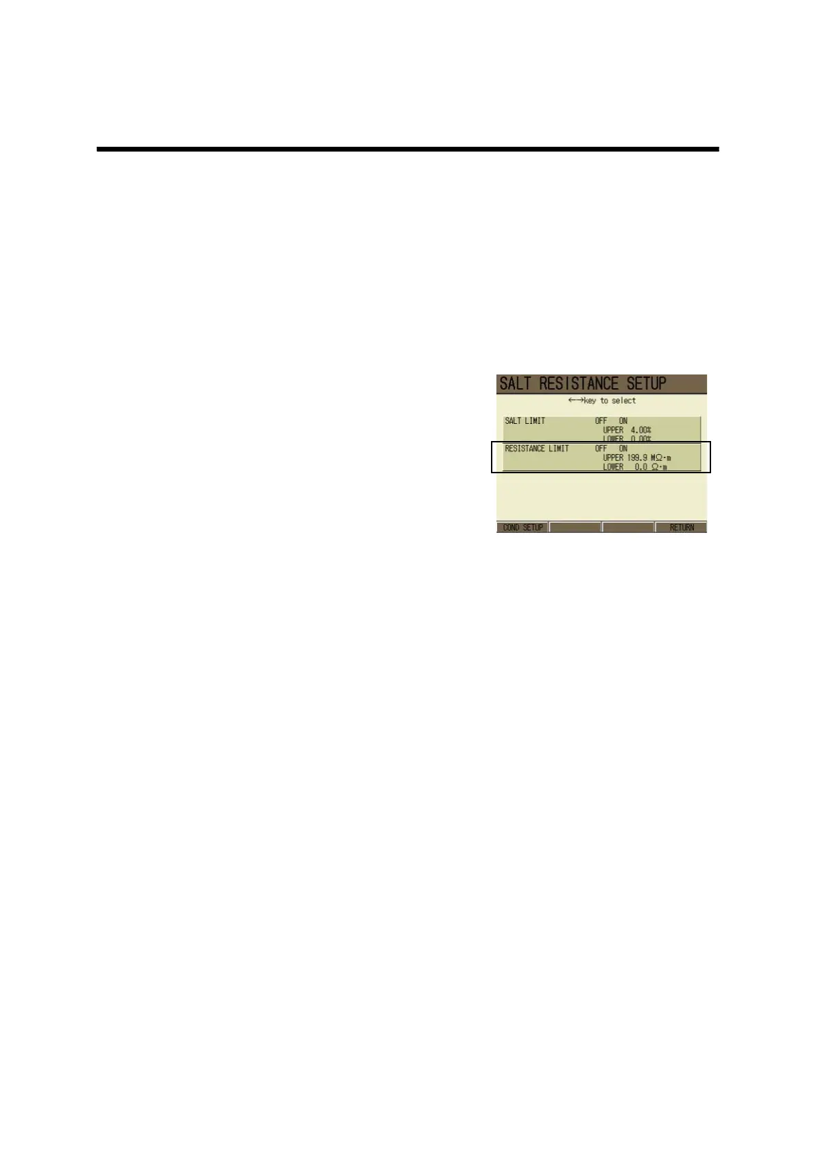
The SALT RESISTANCE SETUP
screen appears.
2. In the SALT RESISTANCE SETUP
screen, press ↑or ↓ key to select
the RESISTANT LIMIT option, and
press ← or → key to select ON or
OFF.
3. Press F4 (RETURN).
The setting is reflected, and the Mea-
surement screen is displayed.
Setting alarm conditions
By selecting ON in the above step 2, the alarm conditions can be set.
According to the set values, the display automatically selects to appropriate unit
1. Press the ENTER key.
2. The cursor moves to the upper limit value setting field.
3. Press the ENTER key again.
The display color at the setting part changes, and the values can be input by pressing ↑
or ↓ key.
Setting range: 0.0 Ω•m to 199.9 MΩ•m
By pressing ← or → key, switch the auxiliary unit.
4. Press the ENTER key.
The setting is determined, and the display color of the set part changes.
5. Press ↓ key to go to the lower limit field.