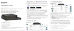
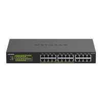
S350 Series 24-Port (PoE+) and 48-Port Gigabit Ethernet Smart Managed Pro Switches
Manage Device Security User Manual263
Note: For L4 port options, two rules are created (one for TCP and one for UDP).
7. In the Sequence Number field, enter a whole number in the range from 1 to 2147483647
that is used to identify the rule.
8. From the Action menu, select Permit or Deny to specify the action that must be taken if a
packet matches the rule’s criteria.
9. From the Match Every
menu, select one of the following options:
• False. Packets do not need to match the selected ACL and rule. With this selection,
you can add a destination MAC address, destination MAC mask, and VLAN.
• T
rue. All packets must match the selected ACL and rule and are either permitted or
denied. In this case, since all packets match the rule, the option of configuring other
match criteria is not offered.
10. Specify the additional match criteria for the selected
ACL type.
The rest of the rule match criteria fields available for configuration depend on the selected
ACL type. For information about the possible match criteria fields, see the following table.
ACL Based On Fields
• Destination MAC. Specify the destination MAC address to compare against
an Ethernet frame. The format is xx:xx:xx:xx:xx:xx. The BPDU keyword
might be specified using a destination MAC address of 01:80:C2:xx:xx:xx.
• Destination
MAC Mask. Specify the destination MAC address mask, which
represents the bits in the destination MAC address to compare against an
Ethernet frame.
The format is xx:xx:xx:xx:xx:xx. The BPDU keyword might
be specified using a destination MAC mask of 00:00:00:f
f:ff:ff.
• VLAN. Specify the VLAN ID to match within the Ethernet frame.
• Source MAC. Specify the source MAC address to compare against an
Ethernet frame. The format is xx:xx:xx:xx:xx:xx.
• Source MAC
Mask. Specify the source MAC address mask, which
represents the bits in the source MAC address to compare against an
Ethernet frame.
The format is (xx:xx:xx:xx:xx:xx).
• VLAN. Specify the VLAN ID to match within the Ethernet frame.
• Destination
IP Address. Specify the destination IP address.
• Destination IP Mask. Specify the destination IP address mask.
• Source IP Address. Specify the source IP address.
• Source IP Mask. Specify the source IP address mask.
• Destination L4 port (Protocol). Specify the destination IPv4 L4 port
protocol.
• Destination L4 port (Value). Specify the destination IPv4 L4 port value.
• Source L4 port (Protocol). Specify the source IPv4 L4 port protocol.
• Source L4 port (Value). Specify the source IPv4 L4 port value.
Destination MAC
Source MAC
Destination IPv4
Source IPv4
Destination IPv4 L4 Port
Source IPv4 L4 Port
 Loading...